3 connecting output devices – GeoVision GV-AS2120 IP Control Panel User Manual
Page 116
114
5.2.3 Connecting Output Devices
Up to 24 output devices can be connected to GV-AS410 / 4110 / 810 / 8110. Check if your
output device meets the following absolute maximum ratings before connecting it to output
terminal block.
Outputs
Outputs 1-16
Outputs 17-24
Breakdown Voltage
110V AC – 250V AC, 30V DC 30V DC
Continuous Load Current
3A (AC), 3A (DC)
1A
Note:
Absolute Maximum Ratings are those values beyond which damage to GV-
AS410 / 4110 / 810 / 8110 circuit board may occur. Continuous operation at the
absolute rating level may affect GV-AS410 / 4110 / 810 / 8110’s stability.
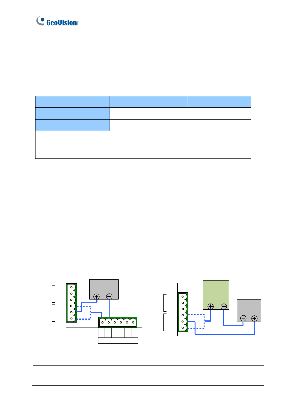
To connect an output device:
Connect the (+) point on the output device to COM on GV-AS410 / 4110 / 810 / 8110,
connect the two (-) points of the output device and the power supply together, and connect
the (+) point on the power supply to the NO or NC of GV-AS410 / 4110 / 810 / 8110 based
on the state of the output device.
There are two ways to supply power to the output device:
⚫
Use the power outputs on the GV-AS Controller:
The total power consumption of the
output devices and readers connected to GV-AS Controller must be under
3.5A
for GV-
AS410 / 4110 or
5A
for GV-AS810 / 8110. The output device must be a 12V device.
⚫
Connect an external power supply:
Connect an external power supply if the total
power consumption exceeds 3.5A / 5A or if the output device requires higher current.
External
Power
Supply
OUT2
OUT1
NO
COM
NC
NO
COM
NC
12V OUTPUT
12
V
G
N
D
12
V
G
N
D
12
V
G
N
D
OUT2
OUT1
NO
COM
NC
NO
COM
NC
Output
Device
Output
Device
Figure 5-5
Note:
If you want to use the power outputs on the GV-AS Controller, note that the maximum
current of the individual voltage output is 12V, 0.9A.