2 installation – GeoVision GV-AS2120 IP Control Panel User Manual
Page 26
24
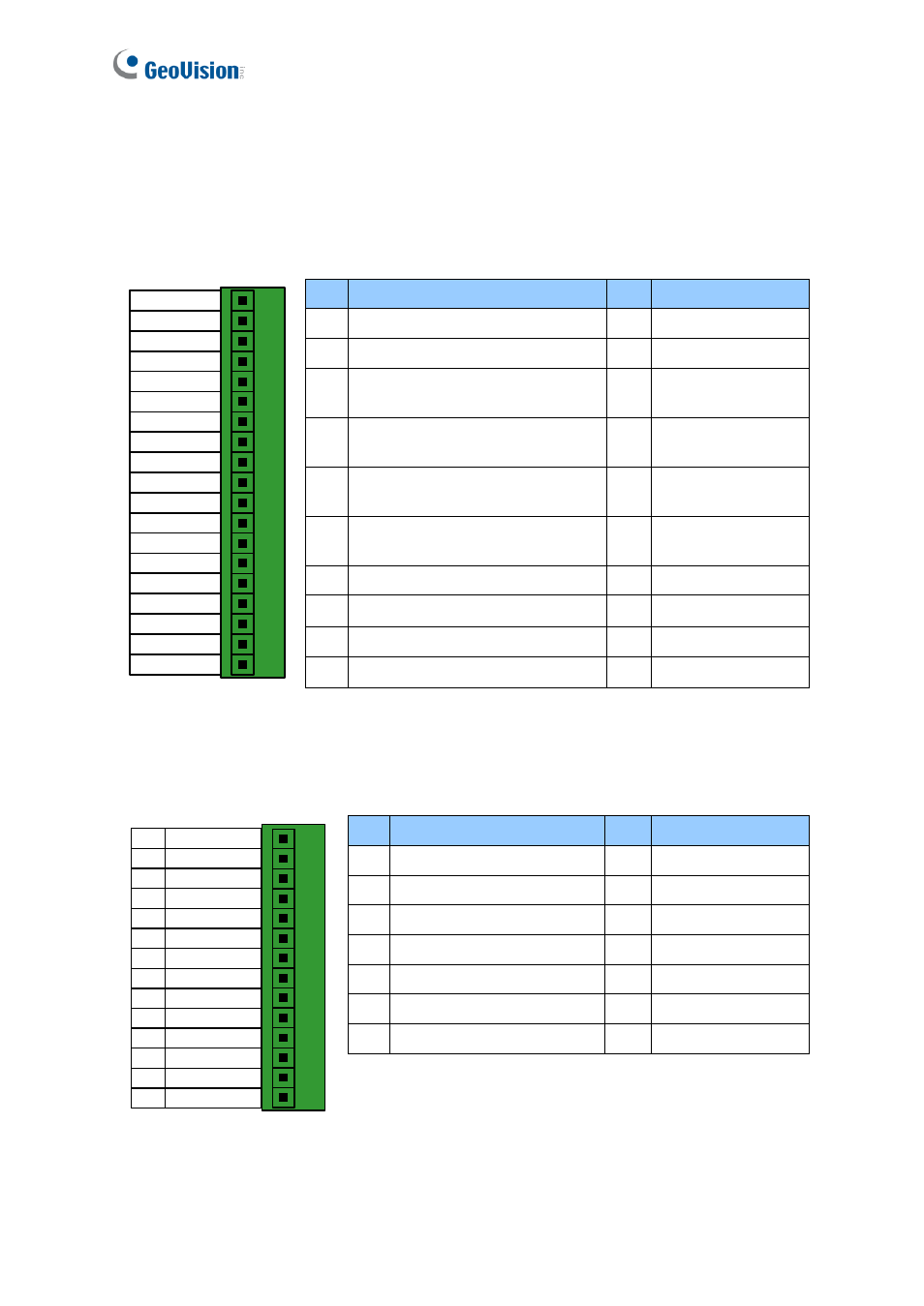
1.2 Installation
Open the GV-AS100 / 1010 to access the terminal block.
GV-AS100
19 Door NO
18 Door NC
17 Door COM
16 Alarm NO
15 Alarm COM
14 IN COM
13 IN3 Fire
12 IN2 Button
11 IN1 Sensor
10 GND
9 PWR Out 12V
8 Data1
7 Data0
6 RS485 B-
5 RS485 B+
4 RS485 A-
3 RS485 A+
2 GND
1 PWR In 12V
Pin Function
Pin Function
1
12V Power
11 Sensor IN1
2
GND
12 Button IN2
3
RS-485 A+ for ASBox / ASNet
or PC connection
13 Fire IN3
4
RS-485 A-for ASBox / ASNet or
PC connection
14 IN COM
5
RS-485 B+ for GV-Reader
connection
15 Alarm COM
6
RS-485 B- for GV-Reader
connection
16 Alarm NO
7
Wiegand Data 0
17 Door COM
8
Wiegand Data 1
18 Door NC
9
12V Power Supply
19 Door NO
10 GND
Figure 1-5
GV-AS1010
Door NC
Door NO
Door COM
Alarm NC
Alarm NO
Alarm Com
IN COM
Input Fire
Input Button
Input Sensor
RS485 -
RS485 +
GND
PWR In 12V
1
2
3
4
5
6
7
8
9
10
11
12
13
14
Pin Function
Pin Function
1
Door NC
8
Input Fire
2
Door NO
9
Input Button
3
Door COM
10 Input Sensor
4
Alarm NC
11 RS485 -
5
Alarm NO
12 RS485 +
6
Alarm Com
13 GND
7
IN COM
14 PWR In 12V
Figure 1-6