E connecting output devices – GeoVision GV-AS2120 IP Control Panel User Manual
Page 191
Optional Devices
189
9
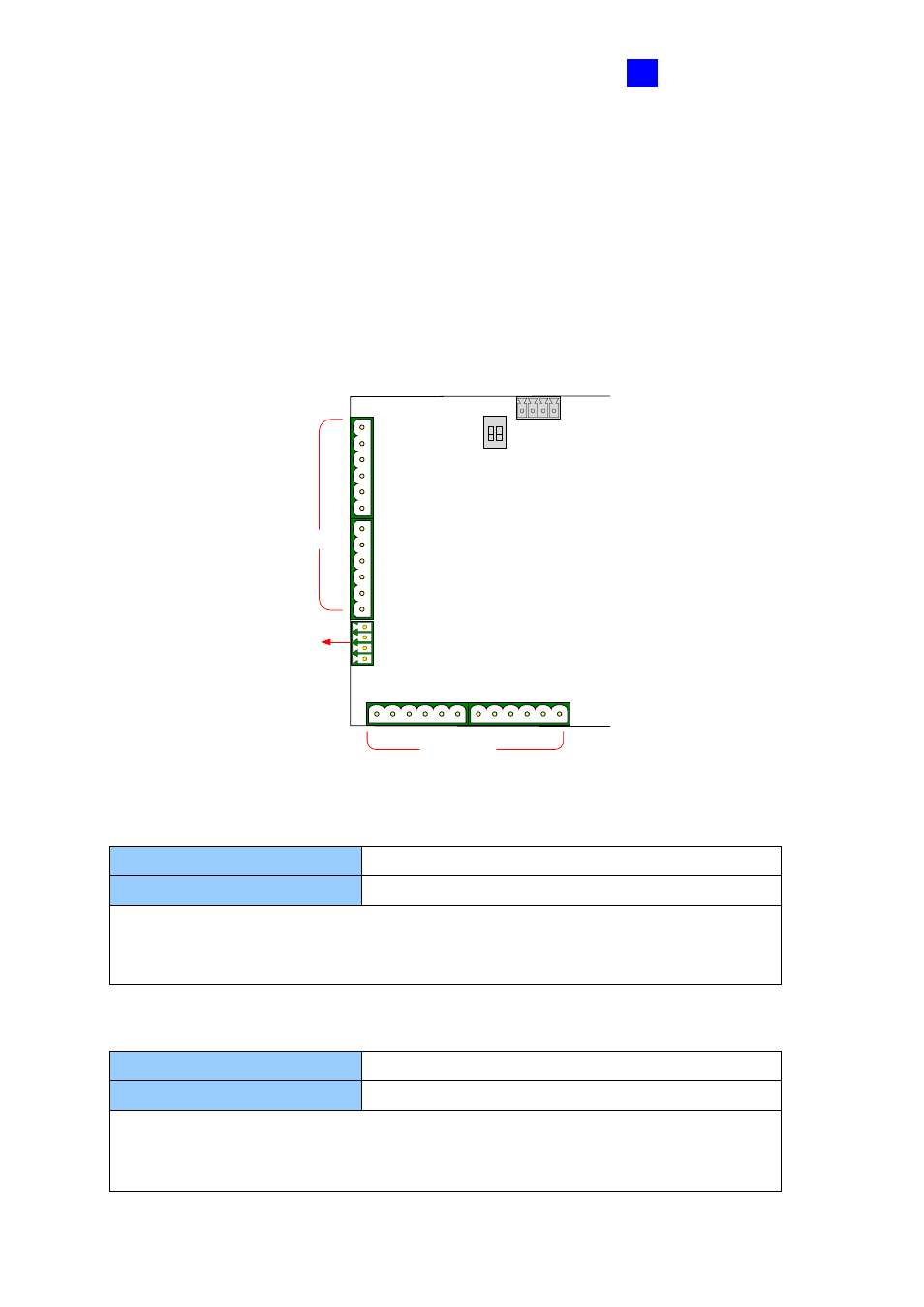
9.1.4.E Connecting Output Devices
GV-ASBox provides 8 outputs and 2 auxiliary power outputs of 12V DC. The outputs are
divided into two groups,
outputs 1 ~ 4
and
outputs 5 ~ 8
. Before connecting, make sure if
your output device meets any of the two different absolute maximum ratings listed below.
Additionally, you can
wire the light switch to the outputs 5 ~ 8
for lighting control. When
the access is granted, the light is turned on; when the exit is granted, the light is turned off.
See
To combine door access with relay activation
below.
1 2
ON
NO5
COM5
NC5
NO6
COM6
NC6
NO7
COM7
NC7
NO8
COM8
NC8
12V
12V
GND
GND
NC4
COM4
NO4
NC3
COM3
NO3
NC2
COM2
NO2
NC1
COM1
NO1
Output 1 ~ 4
Output 5 ~ 8
Auxiliary Power Output
Figure 9-5
Outputs 1-4: Absolute Maximum Ratings
Breakdown Voltage
277V AC, 30V DC
Continuous Load Current
5A (NO), 3A (NC)
Note:
Absolute Maximum Ratings are those values beyond which damage to GV-
ASBox circuit board may occur. Continuous operation of GV-ASBox at the absolute
rating level may affect GV-ASBox reliability.
Outputs 5-8: Absolute Maximum Ratings
Breakdown Voltage
240V AC, 30V DC
Continuous Load Current
16A (NO), 8A (NC)
Note:
Absolute Maximum Ratings are those values beyond which damage to GV-
ASBox circuit board may occur. Continuous operation of GV-ASBox at the absolute
rating level may affect GV-ASBox reliability.