GeoVision GV-AS2120 IP Control Panel User Manual
Page 32
Advertising
30
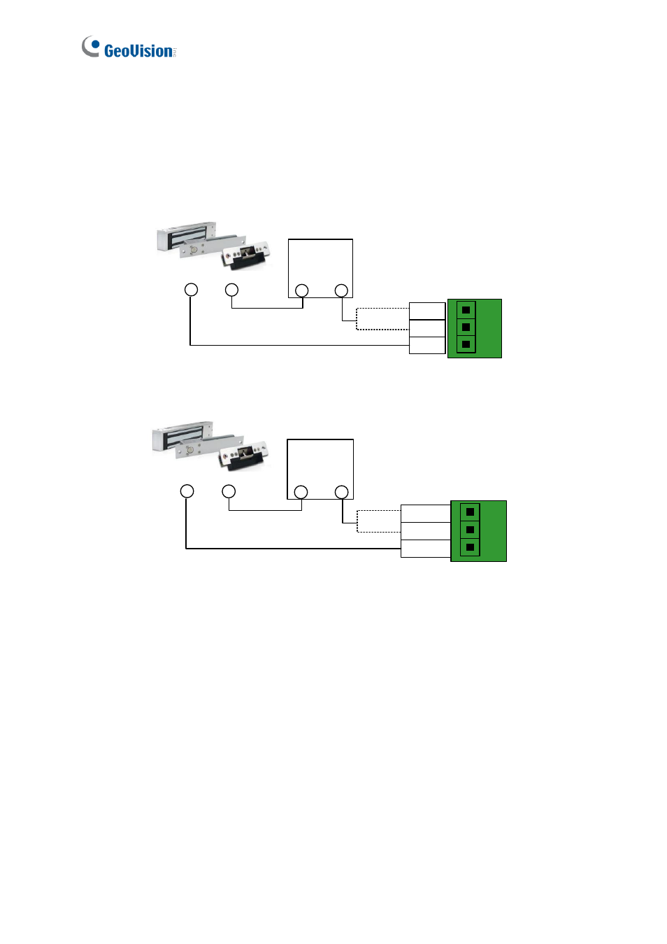
To connect an output device:
The example below illustrates the connection of a locking device to GV-AS100 / 1010.
Connect the (+) point on the locking device to the Door COM on GV-AS100 / 1010, connect
the two (-) points of the locking device and the external power supply together, and connect
the (+) point on the external power supply to the Door NO or Door NC on GV-AS100 / 1010
based on the state of the locking device.
Locking Device
External
Power Supply
+
-
-
Door
19 NO
Door
18 NC
Door
17 COM
+
GV-AS100
Locking Device
External
Power Supply
+
-
-
1 Door NC
2 Door NO
3 Door COM
+
GV-AS1010
Figure 1-9
Advertising