Altera DDR Timing Wizard User Manual
Page 68
3–8
Altera Corporation
DDR Timing Wizard User Guide
November 2007
Introduction
f
AN328: Interfacing DDR2 SDRAM in Stratix II,
Stratix II GX, and Arria GX Devices
.
Ideal margin is calculated by adding the smallest setup and smallest
hold time margin between the fast and slow timing models and
dividing the total by two to show a balanced setup and hold margin,
as shown in the following equation:
Ideal margin = (smallest setup margin + smallest hold margin)/2
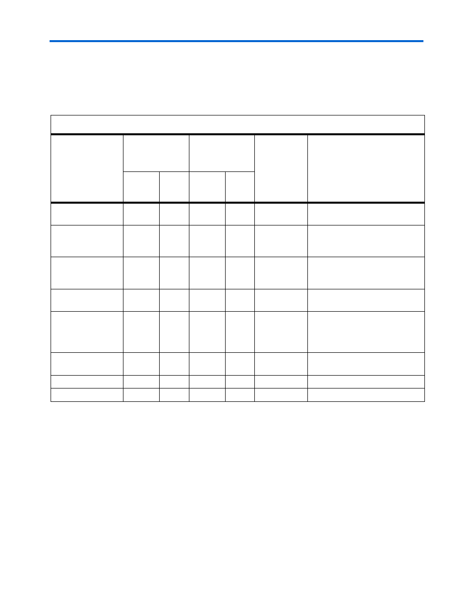
Table 3–2. Memory Interface Paths Analyzed by the Script
DDR2/DDR
SDRAM
(DQS mode)
DDR2/DDR
SDRAM
(non-DQS mode)
QDRII+/QDRII
SRAM and
RLDRAMII
(DQS and
non-DQS
mode)
Description
Fedback
PLL
One
PLL
Fedback
PLL
One
PLL
Read Capture
v
v
v
v
v
Margin at the read capture
registers
Fedback Clock
v
N/A
N/A
N/A
Margin at the resynchronization
registers clocked by the fedback
PLL output
Resynchronization
Clock
v
v
v
Margin at the resynchronization
registers clocked by the system
PLL output
Recovery/Removal
v
v
N/A
N/A
N/A
Margin for the DQS postamble
registers
Postamble
v
N/A
N/A
N/A
Margin for the registers, clocked
by the system clock, whose
output goes to the postamble
registers
t
DQSS
v
v
v
v
N/A
Margin for skew relationship
between CK and DQS signals
Write Capture
v
v
v
v
v
Margin for write data
Address/Command
v
v
v
v
v
Margin for address and command
(1)
Fedback clock in this implementation is used for read capture, not for resynchronization. The script analyzes this
as read capture.
(2)
Quartus II software reports the margin because this path is a clock domain transfer between two outputs of the
same PLLs.
(3)
RLDRAM II and QDRII+/QDRII SRAM interfaces do not require resynchronization clocks as the Altera IP
MegaCores use a FIFO to resynchronize data to the system clock.