Altera DDR Timing Wizard User Manual
Page 69
Altera Corporation
3–9
November 2007
DDR Timing Wizard User Guide
Using the dtw_timing_analysis.tcl Script
The PLL name column shows which PLL clock tap is used for the
path.
■
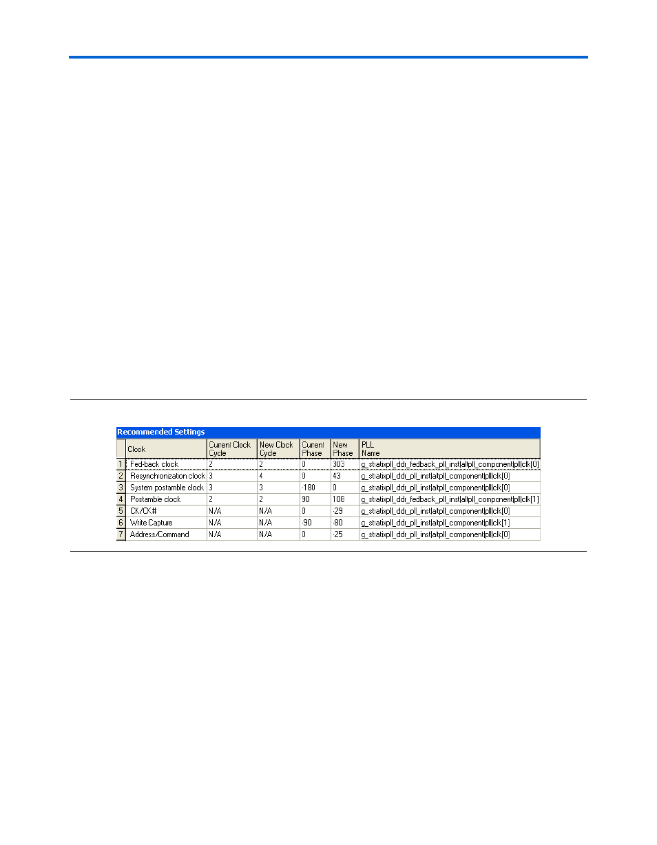
Recommended Settings
This panel shows the current and new clock cycle and phase shift
selections for the interface. The current shift and clock cycle show
what are currently set in the DTW. The new shift and clock cycle are
calculated by the dtw_timing_analysis.tcl script as the
recommended settings. Only read side paths have clock cycle
selections. You should follow the clock cycle and phase shift
selection suggested in the Recommended Settings whenever
possible for the most optimal settings for the design.
The new phase shifts shown are the ideal phase shift to achieve
balanced setup and hold margin. However, note that the PLL may
not be able to achieve that particular phase shift. If the current phase
shift and the new phase shift differs by less than 15°, your design
already uses the optimal settings.
shows an example of the Recommended Settings panel.
Figure 3–4. Example Design Recommended Settings
The PLL name column shows which PLL clock tap is used for the
path. Note that the same PLL output tap may be used for multiple
paths, so be careful when changing the phase shift on this PLL
output as it will change the margin on the other tap.