5 input/output 1 & output 2, 1 relay output (form a, normally open), 2 logic (ssr drive) output – Super Systems 3 Series User Manual
Page 10: 3 dc output, 4 triac output, 5 logic contact closure input (i/o 1 only), 6 remote setpoint input, 7 output 3, 8 summary of dc outputs, Input/output 1 & output 2
Operations Manual
Series 3
10
2.5
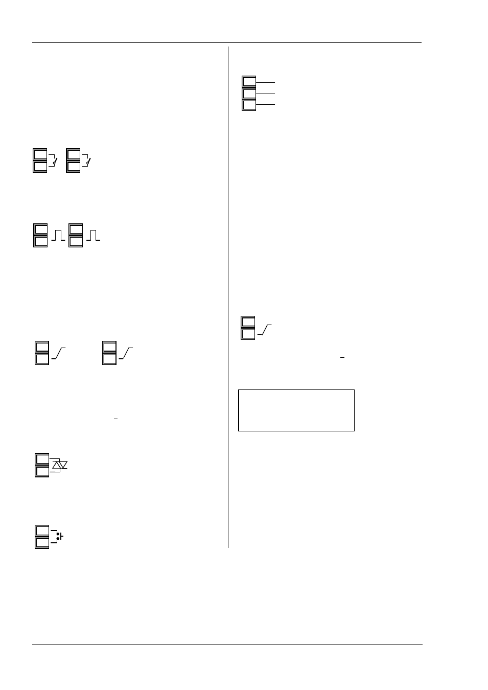
Input/Output 1 & Output 2
These outputs can be logic (SSR drive), or relay, or mA dc. In
addition the logic output 1 can be used as a contact closure
input.
For input/output functions, see Quick Start Code in section
4.1.1.
2.5.1
Relay Output (Form A, normally open)
•
Isolated output 240Vac CAT II
•
Contact rating: 2A 264Vac
resistive
2.5.2
Logic (SSR drive) Output
•
Not isolated from the sensor
input
•
Output ON state: 12Vdc at
40mA max
•
Output OFF state: <300mV,
<100µA
•
The output switching rate must be set to prevent
damage to the output device in use. See parameter
1.PLS or 2.PLS in section 5.
2.5.3
DC Output
•
Not isolated from the sensor input
•
Software configurable: 0-20mA or 4-20mA.
•
Max load resistance: 500Ω
•
Calibration accuracy: +(<1% of reading + <100µA)
2.5.4
Triac Output
•
Isolated output 240Vac CATII
•
Rating: 0.75A rms, 30 to 264Vac resistive
2.5.5
Logic Contact Closure Input (I/O 1 only)
•
Not isolated from the sensor input
•
Switching: 12Vdc at 40mA max
•
Contact open > 500Ω. Contact closed <
150Ω
2.6 Remote Setpoint Input
• There are two inputs; 4-20mA and 0-10 Volts which can be
fitted in place of digital
communications
• It is not necessary to fit an
external burden resistor to the
4-20mA input
• If the 4-20mA remote setpoint input is connected and
valid (>3.5mA; < 22mA) it will be used as the main
setpoint. If it is not valid or not connected the controller
will try to use the Volts input. Volts sensor break occurs at
<-1; >+11V. The two inputs are not isolated from each
other
• If neither remote input is valid the controller will fall back
to the internal setpoint, SP1 or SP2 and flash the alarm
beacon. The alarm can also be configured to activate a
relay or read over digital communications.
• To calibrate the remote setpoint, if required, see section
• A local SP trim value is available in access level 3.
2.7
Output 3
Output 3 will be a mA output.
DC Output
•
Isolated output 240Vac CAT II
•
Software configurable: 0-20mA or 4-
20mA
•
Max load resistance: 500Ω
•
Calibration accuracy: 0.5%, +100µA
2.8
Summary of DC Outputs
OP1
Non-isolated
OP2
Non-isolated
OP3
Non-isolated
OP4
Non-isolated
1(2) A
1(2)B
OP1
OP2
1A
1B
2A
2B
+
-
OP2
2A
2B
+
-
OP1
1A
1B
OP1
1A
1B
0-10 Volts
4-20 mA
Common
HD
HE
HF
+
-
OP3
3A
3B
+
-
OP1
1A
1B
+
-
OP2
2A
2B