3 to calibrate rtd input, To calibrate rtd input, N o n e – Super Systems 3 Series User Manual
Page 86
Operations Manual
Series 3
86
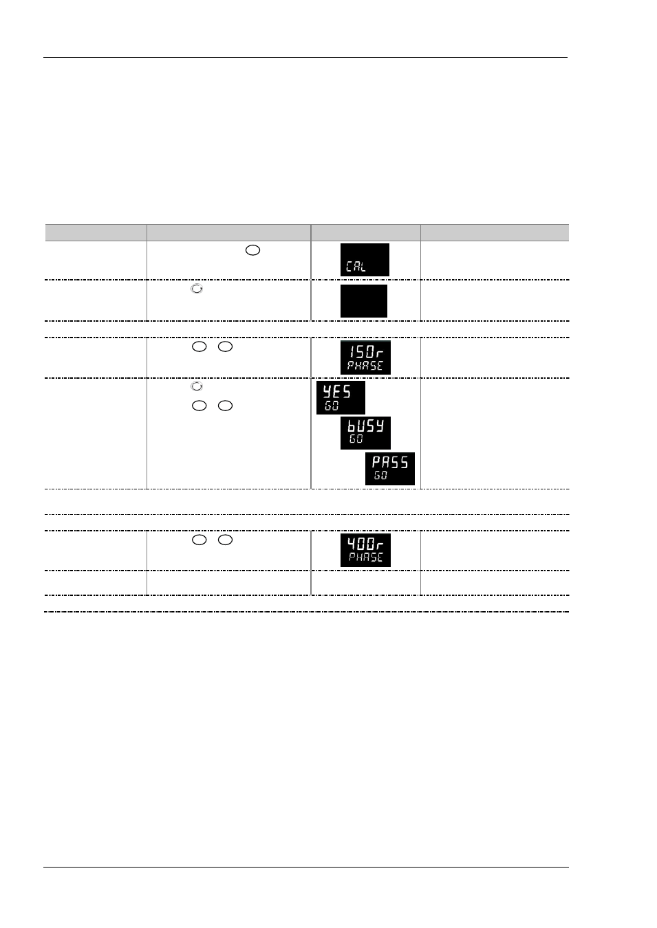
14.3.3
To Calibrate RTD Input
The two points at which the RTD range is calibrated are 150.00Ω and 400.00Ω.
Before starting RTD calibration:
•
A decade box with total resistance lower than 1K must be connected in place of the RTD as indicated on the connection
diagram in section 15.1.4 before the instrument is powered up. If at any time the instrument was powered up without this
connection then at least 10 minutes must elapse from the time of restoring this connection before RTD calibration can take
place.
•
The instrument should be powered up for at least 10 minutes.
•
Before calibrating the RTD input the mV range must be calibrated first
Operation
Do This
Display View
Additional Notes
Select the Calibration List
header
1.
From any display press
as many
times as necessary until the ‘C A L ’ page header
is displayed.
Scrolling display ‘
C A L I B R A T I O N
L I S T
’
Select the calibration phase
2.
Press
to select ‘P H A S E ’
n o n e
p h a s e
Scrolling display ‘
C A L I B R A T I O N
p h a s e
’
Set the decade box for 150.00Ω
Select the low calibration
point (150Ω)
3.
Press
or
to choose ‘150r
Calibrate the low point
4.
Press
to select ‘GO’
5.
Press
or
to choose ‘YES’
Scrolling display ‘
C A L I B R A T I O N
s t a r t
’
The controller automatically calibrates to the injected 150.00Ω input. The display will show
busy
then
pass
(if calibration is successful) or ‘
FAIL’
if not. Fail may be due
to an incorrect input resistance
Set the decade box for 400.00Ω
Select the high calibration
point (400Ω)
7.
Press
or
to choose ‘400r
Calibrate the high point
8.
Repeat 5 and 6 above to calibrate the high
point
The controller will again automatically calibrate to the injected 400.00Ω input. If it is not successful then ‘
FAIL’
will be displayed