4 access parameters, Access parameters – Super Systems 3 Series User Manual
Page 29
Series 3
Operations Manual
29
6.4
Access Parameters
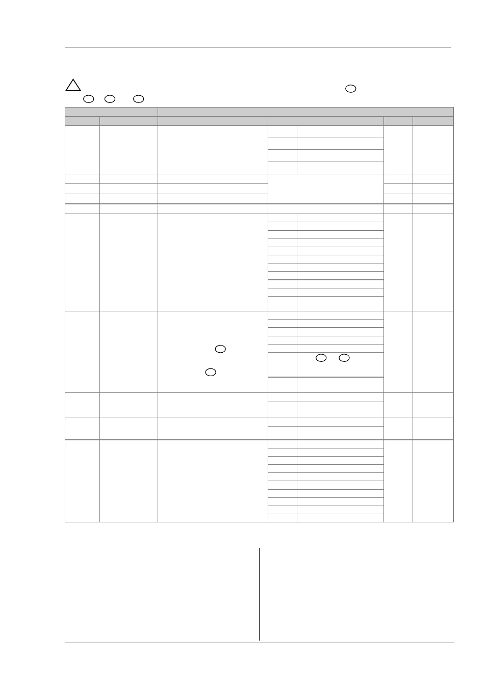
The following table summarizes the parameters available under the ACCESS list header
!
The Access List can be selected at any time when in configuration level by holding
key down for 3 seconds, then
press
or
with
still held down.
ACCESS LIST
‘ A C C S ’
Name
Scrolling Display
Parameter Description
Values Allowed
Default
Access Level
G O T O
SELECT ACCESS
LEVEL
Allows you to change the access level of the
controller. Passwords prevent unauthorised
change
Lev.1
Operator level 1
Lev.1
Conf
Lev.2
Operator level 2
Lev.3
Operator level 3
Conf
Configuration level
LEV2.P
LEVEL 2 PASSCODE
The Level 2 passcode
0-9999
0
= no passcode will be requested
2
Conf
LEV3.P
LEVEL 3 PASSCODE
The Level 3 passcode
3
Conf
CONF.P
CONFIG PASSCODE
To set a Configuration level passcode
4
Conf
I D
CUSTOMER ID
To set the identification of the controller
0-9999
Conf
H O M E
HOME DISPLAY See
Note 1
To configure the parameter to be displayed
in the lower line of the HOME display
Std
Setpoint
Std
Conf
OP
Output demand
Tr
Time remaining
ELAP
Time elapsed
AL
Alarm 1 setpoint
Ct
Current transformer
CLr
No parameter
tmr
Time remaining
t.sp
Target setpoint
no.PV
PV is not displayed
Stby
PV is not displayed when the
controller is in standby mode
K . L O C
KEYBOARD LOCK
To limit operation of the front panel buttons
when in operator levels.
If ALL has been selected, then to
restore access to the keyboard, power up
the controller with the
button held
down and enter the configuration level
passcode. This will take you to the Quick
Code mode. Press
to EXIT and select
YES
. The front panel buttons can then be
operated as normal.
none
Unlocked
none
Conf
ALL
All buttons locked
Edit
Edit keys locked See Note 2
Mod
Mode keys locked See Note 3
Man
Manual mode locked
Stby
Press
and
to toggle
between normal operation and
standby mode
tmr
FEATURE UNAVAILABLE
C O L D
COLD START
ENABLE/ DISABLE
Use this parameter with care.
When set to yes the controller will return to
factory settings on the next power up
No
Disable
No
Conf
YES
Enable
s t b y . t
STANDBY TYPE
Turn ALL outputs off when the controller is
in standby mode. Typical use when event
alarms are used to interlock a process.
Abs.a
Absolute alarms to remain active
abs.a
Conf
Off
All alarms off in standby
m e t e r
METER
CONFIGURATION
See Note 4
To configure the analogue meter to indicate
any one of the parameters listed.
OFF
Meter display disabled
Conf
HEAT
Heat Output demand
COOL
Cool output demand
w.sp
Working setpoint
pV
Process value
Op
Heat output demand
C.OP
Cool output demand
err
Error (SP – PV)
amps
Output current
LCur
Load current from CT
Note 1
Home Display Configuration
The upper display always shows PV, the lower display is
configurable.
Std
In automatic control the lower display shows setpoint.
In manual mode output power is shown.
OP
Output power is shown in both automatic and manual
modes.
AL1
First configured alarm setpoint
Ct
CT current
CLr
Blank display
no.pv
The upper display is blank
Stby
The upper display blanks when the controller is in
standby mode.
Note 2
Edit keys locked. Parameters cannot be changed but
viewed only.