5 high and low cutback, 6 manual reset, 7 control action – Super Systems 3 Series User Manual
Page 50: 8 loop break, 9 cooling algorithm, 3 tuning, High and low cutback, Manual reset, Control action, Loop break
Operations Manual
Series 3
50
11.2.5
High and Low Cutback
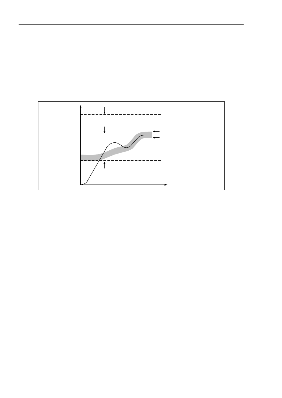
Cutback high ‘CBHI’ and Cutback low ‘CBLO’ are values that modify the amount of overshoot, or undershoot, that occurs during
large step changes in PV (for example, under start-up conditions). They are independent of the PID terms which means that the
PID terms can be set for optimal steady state response and the cutback parameters used to modify any overshoot which may be
present.
Cutback involves moving the proportional band towards the cutback point nearest the measured value whenever the latter is
outside the proportional band and the power is saturated (at 0 or 100% for a heat only controller). The proportional band moves
downscale to the lower cutback point and waits for the measured value to enter it. It then escorts the measured value with full
PID control to the setpoint. In some cases it can cause a ‘dip’ in the measured value as it approaches setpoint, as shown in the
diagram below, but generally decreases the time needed to bring the process into operation.
The action described above is reversed for falling temperature.
If cutback is set to Auto the cutback values are automatically configured to 3*PB.
11.2.6
Manual Reset
In a full three-term controller (that is, a PID controller), the integral term automatically removes the steady state error from the
setpoint. If the controller is set as a PD controller, the integral term will be set to ‘OFF’. Under these conditions the measured
value may not settle precisely at setpoint. The Manual Reset parameter (M R ) represents the value of the power output that will
be delivered when the error is zero. You must set this value manually in order to remove the steady state error.
11.2.7
Control Action
When set to reverse (RE V ) the output increases when the PV is below setpoint. This is the best setting for heating control.
For cooling control only set Control Action to direct (DI R).
11.2.8
Loop Break
The loop is considered to be broken if the PV does not respond to a change in the output. Since the time of response will vary
from process to process the Loop Break Time parameter allows a time to be set before a Loop Break Alarm is initiated. In these
circumstances the output power will drive to high or low limit. For a PID controller, if the PV has not moved by 0.5 x Pb in the
loop break time the loop is considered to be in break. The loop break time is set by the Auto-tune, a typical value is 12 x Td. For
an On/Off controller Loop Break Time is not shown and loop break alarm is inhibited.
11.2.9
Cooling Algorithm
The method of cooling may vary from application to application.
For example, an extruder barrel may be cooled by forced air (from a fan), or by circulating water or oil around a jacket. The
cooling effect will be different depending on the method. The cooling algorithm may be set to linear where the controller output
changes linearly with the PID demand signal, or it may be set to water, oil or fan where the output changes non-linearly against
the PID demand. The algorithm provides optimum performance for these methods of cooling.
11.3
Tuning
In tuning, you match the characteristics (PID parameters) of the controller to those of the process being controlled in order to
obtain good control. Good control means:
•
Stable, ‘straight-line’ control of the PV at setpoint without fluctuation
•
No overshoot, or undershoot, of the PV setpoint
0% output level
Upper cutback point, CBH
Time
Temperature
Lower cutback point, CBL
Setpoint
100% output level