3 example: to set up instrument address, 4 data encoding, 5 parameter modbus addresses – Super Systems 3 Series User Manual
Page 71: Example: to set up instrument address, Data encoding, Parameter modbus addresses
Series 3
Operations Manual
71
13.3
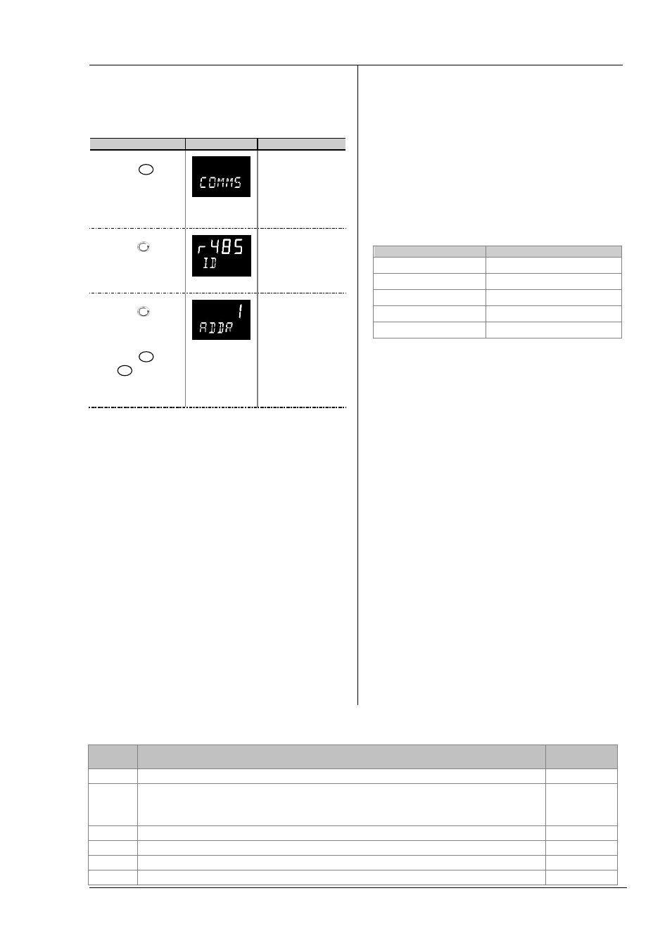
Example: To Set Up Instrument
Address
This can be done in operator level 3
Do This
Display View
Additional Notes
1.
Press
as
many times as
necessary to
select ‘COMMS
LIST’
Scrolling display
‘c o m m s l i s t ’
2.
Press
to
scroll to ‘ID’
Scrolling display
‘i d ’ . This displays
the type of
communications
board fitted
3.
Press
to
scroll to ‘ADDR’
4.
Press
or
to select
the address for
this controller
Up to 254 can be
chosen but note
that no more than
33 instruments
should be
connected in series.
Scrolling display
‘a d d r e s s ’
13.4
DATA ENCODING
Modbus data is normally encoded into a 16 bit signed integer
representation.
Integer format data, including any value without a decimal
point or represented by a textual value (for example ‘off’, or
‘on’), is sent as a simple integer value.
For floating point data, the value is represented as a ‘scaled
integer’, in which the value is sent as an integer which gives
the result of the value multiplied by 10 to the power of the
decimal resolution for that value. This is easiest to
understand by reference to examples:
FP Value
Integer Representation
FP Value
Integer Representation
9.
9
-1.0
10
123.5
1235
9.99
999
It may be necessary for the Modbus master to insert or
remove a decimal point when using these values.
It is possible to read floating point data in a native 32 bit
IEEE format.
For time data, for example, the length of a dwell, the integer
representation depends on the resolution. For ‘hours’
resolution, the value returned is the number of minutes the
value represents, so for example a value of 2:03 (2 hours and
three minutes) would be returned as an integer value of 123.
For ‘minutes’ resolution, the value used is the number of
seconds the value represents, so that 12:09 (12 minutes and
9 seconds) would be returned as 729.
It is possible to read time data in a native 32 bit integer
format, in which case it returns the number of milliseconds
the variable represents regardless of the resolution.
13.5
Parameter Modbus Addresses
Parameter
Mnemonic
Parameter Name
Modbus Address
Decimal
PV.IN
PV (Temperature) Input Value (see also Modbus address 203 which allows writes over Modbus to this variable).
1
TG.SP
Target Setpoint.
NB – do not write continuously changing values to this variable. The memory technology used in this product has a limited
(100,000) number of write cycles. If ramped setpoints are required, consider using the internal ramp rate function or the
remote comms setpoint (Modbus address 26 )in preference.
2
MAN.OP
Manual Output Value
3
WRK.OP
Working Output
4
WKG.SP
Working Setpoint (Read Only)
5
PB
Proportional Band
6