2 offsets, 1 two point offset, Offsets – Super Systems 3 Series User Manual
Page 82: Two point offset
Operations Manual
Series 3
82
Figure -3: Connections for RTD Calibration
The RTD range of the instrument is -200 to 850
O
Set the resistance of the decade box to the minimum range.
For example 0
C. It is,
however, unlikely that it will be necessary to check the
instrument over this full range.
O
Set the resistance of the decade box to the maximum range.
For example 200
C = 100.00Ω. Check the calibration is within
+0.25% of reading + 1LSD.
O
14.2 Offsets
C = 175.86Ω. Check the calibration is
within +0.25% of reading + 1LSD.
The process value can be offset to take into account known
errors within the process. The offset can be applied to any
Input Type (mV, V, mA, thermocouple or RTD).
A single offset can be applied - the procedure is carried out in
the I NP UT list..
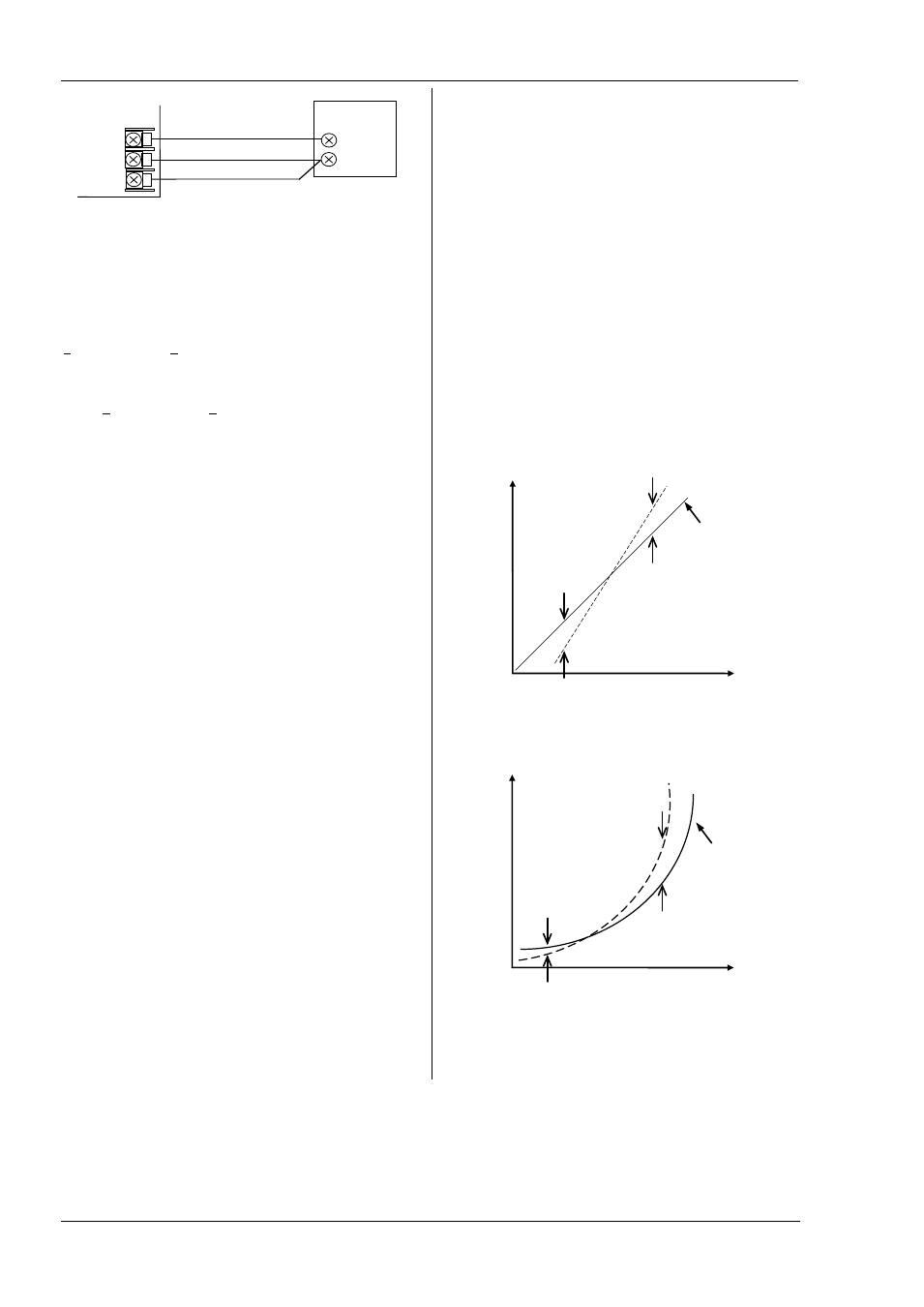
It is also possible to adjust the low and high points as a two
point offset. This can only be done in Level 3 in the ‘Ca l ’
list and is described below.
14.2.1
Two Point Offset
A two point offset adjusts both a low point and a high point
and applies a straight line between them. Any readings
above and below the calibration points will be an extension
of this straight line. For this reason it is best to calibrate with
the two points as far apart as possible as shown in the
example below:
Figure 4 Two Point Offset Applied to Linear and Non-linear Inputs
Matched impedance copper
leads
Decade
Box
Controller
VI
V-
V+
Electrical
Input
Display Reading
High offset
(e.g. 10.0)
Factory
calibration
Low offset (e.g.
8.0)
Electrical
Input
Display Reading
High offset
Factory
calibration
Low offset