3 navigation diagram, Navigation diagram – Super Systems 3 Series User Manual
Page 28
Operations Manual
Series 3
28
6.3
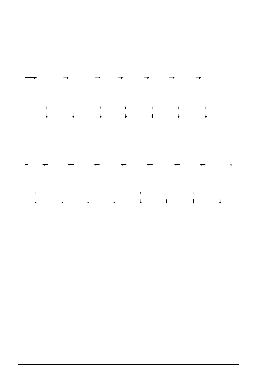
Navigation Diagram
The diagram below shows the all list headings available in configuration level for Series 3 controllers.
The parameters in a list are shown in tables in the following sections of this manual together with explanations of their meanings
and possible use.
For Series 3 controllers additional lists are available, for example Output 3 and Digital Input B
Configuration
IO1 LIST
Output 2 List
AA Relay List
Logic Input a
List
PROCESS
INPUT
LIST
current
transformer List
Control List
Recipe List
Comms List
Timer List
Alarms List
Setpoint List
Calibration List
Access List
Sensor Input
Parameters see
Section 8
Output 1 or
Input 1
Parameters see
Section 9
Output 2
Parameters see
Section 9
AA Relay
(Output 4)
Parameters see
Section 9
Digital Input
Parameters see
Section 9
CT Input
Parameters
Not Supported
Calibration
Parameters see
Section 16
Communications
Parameters see
Section 15
Timer
Parameters see
Section 13
Alarm
Parameters see
Section 12
Control
Parameters see
Section 11
Setpoint
Parameters see
Section 10
Access
Parameters see
Section 6.4
Recipe
Parameters see
Section 14
Level 2
Parameters
Section 5.3