4 calibration parameters, Calibration parameters – Super Systems 3 Series User Manual
Page 90
Operations Manual
Series 3
90
14.4
Calibration Parameters
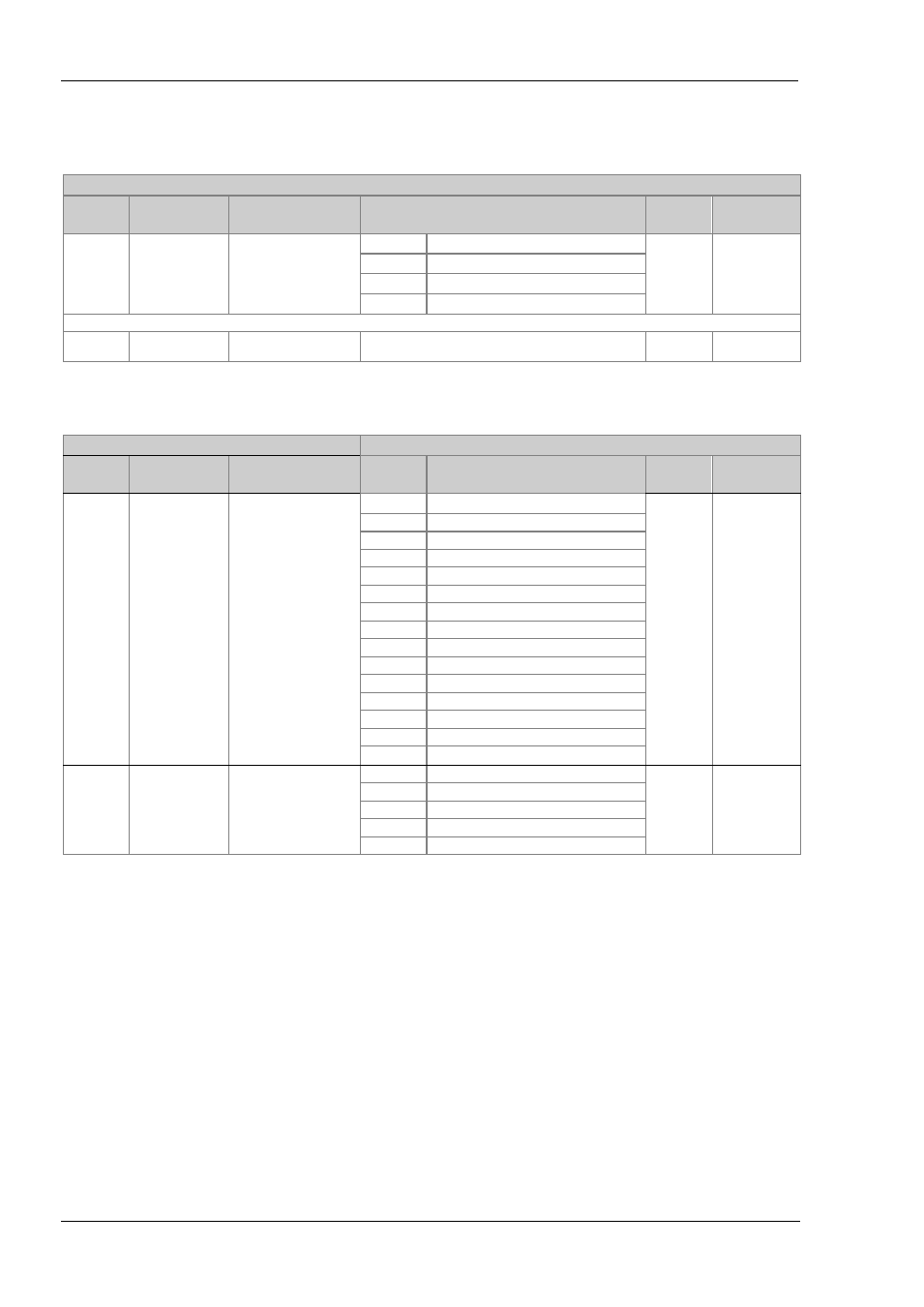
The following table gives the parameters available in the Calibration List.
The User Calibration is available in Level 3 only and is used to calibrate ‘Offset’
CALIBRATION PARAMETER LIST
‘cAL’
Name
Scrolling
Display
Parameter
Description
Value
Default
Access Level
u c a l
USER
CALIBRATION
To select low and high
offset state or reset to no
offsets.
IdLe
Normal operating state
IdLE
L3 only
Lo
Low offset
Hi
High offset
rEST
Remove high and low offsets
The following parameters appear when calibrating the controller ie UCAL = Lo or Hi
c . a d j
CALIBRATION
ADJUST
To set an offset value.
-1999 to 9999
L3 only
Input and Output calibration can only be done in Conf level.
CALIBRATION PARAMETER LIST
‘cAL’
Name
Scrolling
Display
Parameter
Description
Value
Default
Access
Level
p h a s e
CAL PHASE
To calibrate low and high
offset
none
Not selected
none
Conf only
0
Select mV low calibration point
50
Select mV high calibration point
150r
Select PRT low cal point
400r
Select PRT high cal point
CJC
Select CJC calibration
Ct 0
Select CT low cal point
Ct 70
Select CT high cal point
Fact
Return to factory settings
Ima.L
Low mA output from I/O 1
Ima.H
High mA output from I/O 1
2ma.L
Low mA output from output 2
2ma.H
High mA output from output 2
3ma.L
Low mA output from output 3
3ma.H
High mA output from output 3
G O
To start the calibration
sequence
NO
NO
Conf only
Yes
Start
Busy
Calibrating
Pass
Calibration successful
faiL
Calibration unsuccessful