7 autotune at setpoint – heat/cool, 8 manual tuning, Autotune at setpoint – heat/cool – Super Systems 3 Series User Manual
Page 56: Manual tuning
Operations Manual
Series 3
56
11.3.7
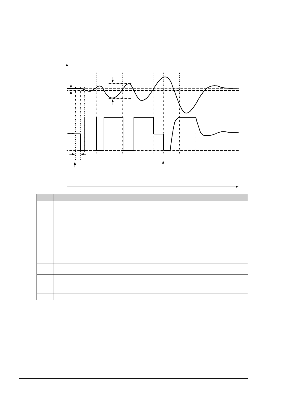
Autotune at Setpoint – Heat/Cool
It is sometimes necessary to tune at the actual setpoint being used. This is allowable in Series 3 series controllers and the
sequence of operation is described below.
Period
Action
A
Start of Autotune.
A test is done at the start of autotune to establish the conditions for a tune at setpoint.
The conditions are that the SP must remain within 0.3% of the range of the controller if ‘PB.UNt’ is set to ‘Percent’. If
‘PB.UNT’ is set to ‘Eng’ then the SP must remain within +1 engineering unit (1 in 1000). Range is defined as ‘RNG.HI’ –
‘RNG.LO’ for process inputs or the range defined in section 8.1.1 for temperature inputs.
A to B
The output is frozen at the current value for one minute and the conditions are continuously monitored during this
period. If the conditions are met during this period autotune at setpoint is initiated at B. If at any time during this period
the PV drifts outside the condition limits a tune at setpoint is abandoned. Tuning is then resumed as a tune from above
or below setpoint depending on which way the PV has drifted.
Since the loop is already at setpoint there is no need to calculate a Tune Control Setpoint – the loop is forced to oscillate
around the Target Setpoint
C to G
Initiate oscillation - the process is forced to oscillate by switching the output between the output limits. From this the
period of oscillation and the peak to peak response is measured. PID terms are calculated
G to H
An extra heat stage is provided and all heating and cooling power is turned off at H allowing the plant to respond
naturally.
Measurements made during this period allow the relative cool gain ‘R2G’ to be calculated.
I
Autotune is turned off and the process is allowed to control at the target setpoint using the new control terms.
For a tune at setpoint autotune does not calculate cutback since there was no initial start up response to the application of
heating or cooling. The exception is that the cutback values will never be returned less than 1.6*PB.
11.3.8
Manual Tuning
If for any reason automatic tuning gives unsatisfactory results, you can tune the controller manually. There are a number of
standard methods for manual tuning. The one described here is the Ziegler-Nichols method.
Adjust the setpoint to its normal running conditions (it is assumed this will be above the PV so that heat only is applied)
Set the Integral Time ‘TI’ and the Derivative Time ‘TD’ to ‘OFF’.
Set High Cutback ‘CBHI’ and Low Cutback ‘CBLO’ to ‘Auto’.
Hysteresis
A – B =1 min
A - Start of
Autotune
I
C
D
E
F
G
H
Low Output
Zero Output
High Output
Target Setpoint
I - End of
Autotune
Pk to Pk
B