1 input/output parameters, 1 input/output 1 list (io-1), Input/output parameters – Super Systems 3 Series User Manual
Page 37: Input/output 1 list (io-1)
Series 3
Operations Manual
37
9.1
Input/Output Parameters
9.1.1
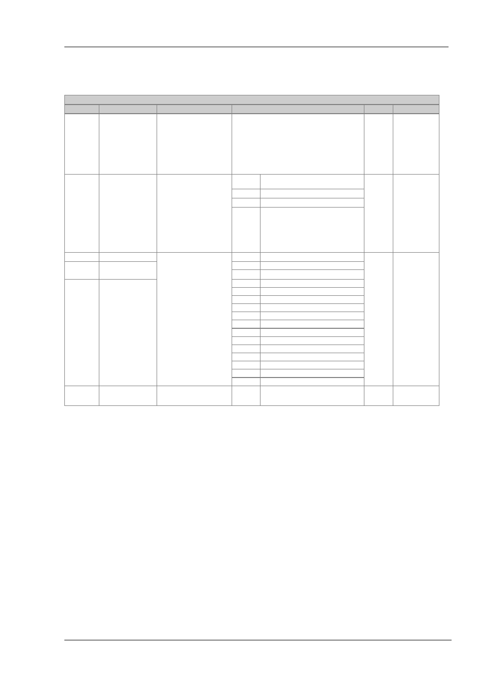
Input/Output 1 List (IO-1)
May be configured as relay, logic ON/OFF. Connections are made to terminals 1A and 1B. OP1 beacon is operated from the IO-1
channel when it is configured as an output.
INPUT/OUTPUT LIST 1 ‘I O -1 ’
Name
Scrolling Display
Parameter Description
Value
Default
Access Level
1 .i d
I/O 1 TYPE
I/O channel 1 hardware type
defined by the hardware
fitted
As
ordered
Read only
1.FUNC
I/O 1 FUNCTION
I/O channel function.
If the instrument is ordered
as valve positioner (codes VC
or VP), only options available
are , none, d.out, UP, or
dwn
Note: If output 1 is set to
Up
ensure the other valve
position output is set to
dwn
and vice versa
none
Disabled. If disabled no further
parameters are shown
As
ordered
Conf
d.out
Digital output
Heat
Heat output
CooL
Cool output
1.SRC.A
I/O 1 SOURCE A
These parameters only
appear when the channel
function is a Digital output,
i.e. 1.FUNC = d.out
Selects an event status to be
connected to the output
channel.
The output status is the
result of an OR of Src A, Src
B, Src C, and Src D
Up to four events can,
therefore, operate the
output
none
No event connected to the output
none
Conf
1.SRC.B
I/O 1 SOURCE B
AL1
Alarm 1
AL2
Alarm 2
1.SRC.C
I/O 1 SOURCE C
AL3
Alarm 3
AL4
Alarm4
ALL.A
All alarms
nw.AL
Any new alarm
Ct.AL
CT alarm, load, leak & overcurrent
Lbr
Loop break alarm
Sbr
Sensor break alarm
t.End
FEATURE UNAVAILABLE
t.run
FEATURE UNAVAILABLE
mAn
Manual status
rmt.F
Remote fail
Pwr.f
Power fail
prg.e
FEATURE UNAVAILABLE
1.SENS
I/O 1 SENSE
To configure the sense of the
input or output channel
nor
Inv
Normal
Inverted
nor
Conf
Note 1:
A DC output may require calibration. This is described in section 15.