14 controller power supply, 15 example heat/cool wiring diagram, Controller power supply – Super Systems 3 Series User Manual
Page 13: Example heat/cool wiring diagram
Series 3
Operations Manual
13
2.14
Controller Power Supply
1. Before connecting the instrument to the power line,
make sure that the line voltage corresponds to the
description on the identification label.
2. Use copper conductors only.
3. For 24V the polarity is not important
4. The power supply input is not fuse protected. This
should be provided externally
•
High voltage supply: 100 to 240Vac, -15%, +10%, 48 to
62
Hz
•
Recommended external fuse ratings are as follows:
For 100-240Vac, fuse type: T rated 2A 250V.
2.15
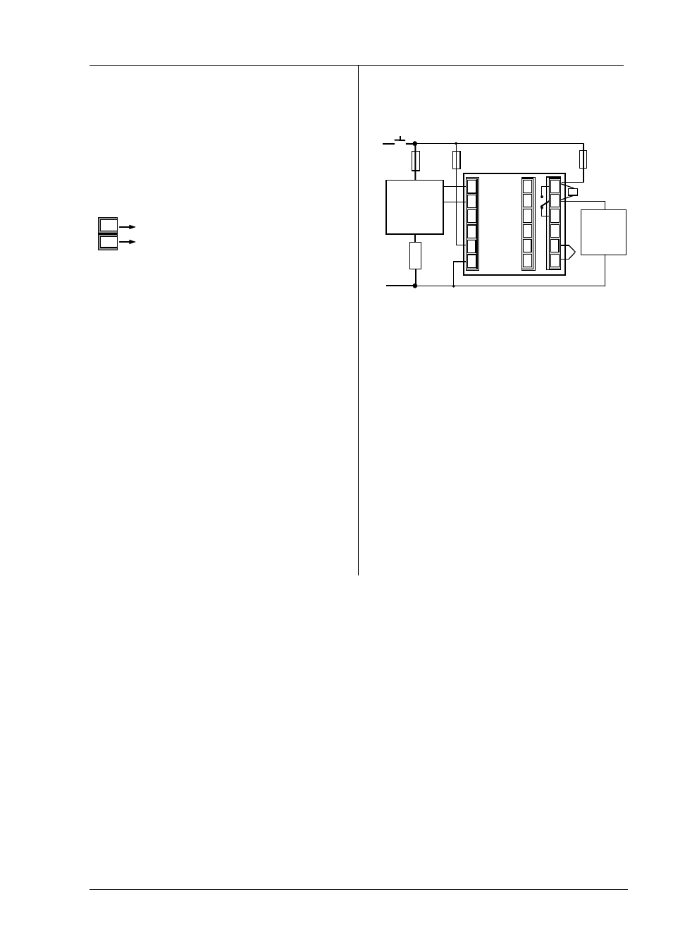
Example Heat/Cool Wiring Diagram
This example shows a heat/cool temperature controller
where the heater control uses a SSR and the cooling control
uses a relay.
Safety requirements for permanently connected equipment
state:
•
A switch or circuit breaker shall be included in the
building installation
•
It shall be in close proximity to the equipment and
within easy reach of the operator
•
It shall be marked as the disconnecting device for the
equipment
A single switch or circuit breaker can drive more than
one instrument
Line
Neutral
Power Supply
L
N
N
Heater
fuse
Relay
output
fuse
Controller fuse
Heater
T/C
Solid State Relay
(e.g. TE10)
Snubber*
L
+
-
Cooling or
alarm relay
J
J
B
CT
C
LA
HD
HE
HF
AA
AB
AC
VI
V+
V-
1A
1B
2A
2B
L
N