Super Systems 3 Series User Manual
Page 23
Series 3
Operations Manual
23
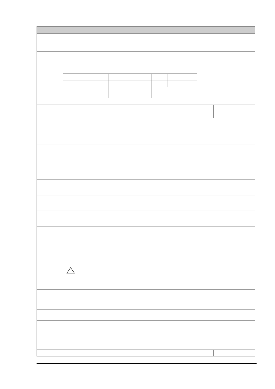
Mnemonic
Scrolling Display and description
Range
DWEL.1
FEATURE UNAVAILABLE
OFF, 0:01 to 99:59 hh:mm or
mm:ss as set by TM.RES
The above three parameters are repeated for the next three program segments, i.e. TSP.2 (3 & 4), RMP.2 (3 & 4), DWEL.2 (3 & 4)
This section applies to Alarms only If an alarm is not configured the parameters do not appear
A1.--- - to A4.-
--
ALARM 1 (2, 3 or 4) SETPOINT sets the threshold value at which an alarm occurs.
Up to four alarms are available and are only shown if configured.
The last three characters in the mnemonic specify the alarm type:
SP.HI to SP.LO
L o
Full Scale Low
H i
Full Scale High
d H i
Deviation High
d L o
Deviation Low
B nd
Deviation Band
r r c
Rising rate of
change
F r c
Falling rate of
change
1
to 9999 units/minute
This section applies to control the parameters. A further description of theses parameters is given in section 11
A.TUNE
AUTOTUNE automatically sets the control parameters to match the process
characteristics.
Off
On
Disable
Enable
PB
PROPORTIONAL BAND sets an output which is proportional to the size of the error
signal. Units may be % or display units.
1 to 9999 display units
Default 20
TI
INTEGRAL TIME removes steady state control offsets by ramping the output up or
down in proportion to the amplitude and duration of the error signal.
Off
to 9999 seconds
Default 360
TD
DERIVATIVE TIME determines how strongly the controller will react to the rate of
change in the process value. It is used to prevent overshoot and undershoot and to
restore the PV rapidly if there is a sudden change in demand.
Off
to 9999 seconds
Default 60 for PID control
Default 0 for VP control
MR
MANUAL RESET applies to a PD only controller i.e. the integral term is turned off.
Set this to a value of power output (from +100% heat, to -100% cool which removes
any steady state error between SP and PV.
-100 to 100%
Default 0
R2G
RELATIVE COOL GAIN adjusts the cooling proportional band relative to the heating
proportional band. Particularly necessary if the rate of heating and rate of cooling are
very different. (Heat/Cool only)
0.1 to 10.0
Default 1.0
HYST.H
HEATING HYSTERESIS Sets the difference in temperature units between heating
turning off and turning on when ON’OFF control is used. Only appears if channel
1(heating) control action is On/Off
0.1 to 200.0 display units
0.2 Default 1.0
HYST.C
COOLING HYSTERESIS Sets the difference in temperature units between cooling
turning off and turning on when ON/OFF control is used. Only appears if channel 2
(cooling) control action is On/Off
0.1 to 200.0 display units
Default 1.0
D.BAND
CHANNEL 2 DEADBAND adjusts a zone between heating and cooling outputs when
neither output is on. Off = no deadband. 100 = heating and cooling off.
Only appears if On/Off control configured.
OFF
or 0.1 to 100.0% of the
cooling proportional band
OP.HI
OUTPUT HIGH limits the maximum heating power applied to the process or a
minimum cooling output.
+100% to OP.LO
1. (2, 3 or 4)
PLS.
OUTPUT 1 (2, 3 or 4) MINIMUM PULSE TIME Sets the minimum on and off time for
the control output.
!
Ensure this parameter is set to a value that is suitable for the output
switching device in use. For example, if a logic output is used to switch a small
relay, set the value to 5.0 seconds or greater to prevent damage to the device due
to rapid switching.
Relay outputs 0.1 to 150.0 seconds
– default 5.0.
Logic outputs Auto to 150.0 -
Default
Auto = 55ms
This section applies to current transformer input only. The CT option is not available on the Series 3.
LD.AMP
LOAD CURRENT is the measured load current when the power demand is on
CT Range
LK.AMP
LEAK CURRENT is the measured leakage current when the power demand is off.
CT Range
LD.ALM
LOAD CURRENT THRESHOLD Sets a low alarm on the load current measured by
the CT. Used to detect partial load failure.
CT Range
LK.ALM
LEAK CURRENT THRESHOLD sets a high alarm on the leakage current measured by
the CT.
CT Range
HC.ALM
OVERCURRENT THRESHOLD Sets a high alarm on the load current measured by
the CT
CT Range
ADDR
ADDRESS - communications address of the controller. 1 to 254
1 to 254
HOME
HOME DISPLAY Defines the parameter which appears in the lower section of the
STD
Standard