3 step 1: installation, 1 panel mounting the controller, 2 panel cut out sizes – Super Systems 3 Series User Manual
Page 7: 3 recommended minimum spacing of controllers, 4 to remove the controller from its sleeve, Step 1: installation, Panel mounting the controller, Panel cut out sizes, Recommended minimum spacing of controllers, To remove the controller from its sleeve
Series 3
Operations Manual
7
1.3
Step 1: Installation
This instrument is intended for permanent installation, for
indoor use only, and to be enclosed in an electrical panel
Select a location which is subject to minimum vibrations the
ambient temperature is within 0 and 55
o
C (32 - 131
o
The instrument can be mounted on a panel up to 15mm
thick.
F) and
humidity 5 to 95% RH non condensing.
To ensure IP65 and NEMA 4 front protection, mount on a
non-textured surface.
Please read the safety information in section 3 before
proceeding.
1.3.1
Panel Mounting the Controller
1. Prepare a cut-out in the mounting panel to the size
shown. If a number of controllers are to be mounted in
the same panel observe the minimum spacing shown.
2. Fit the sealing gasket behind the front bezel of the
controller
3. Insert the controller through the cut-out
4. Spring the panel retaining clips into place. Secure the
controller in position by holding it level and pushing both
retaining clips forward.
5. Peel off the protective cover from the display.
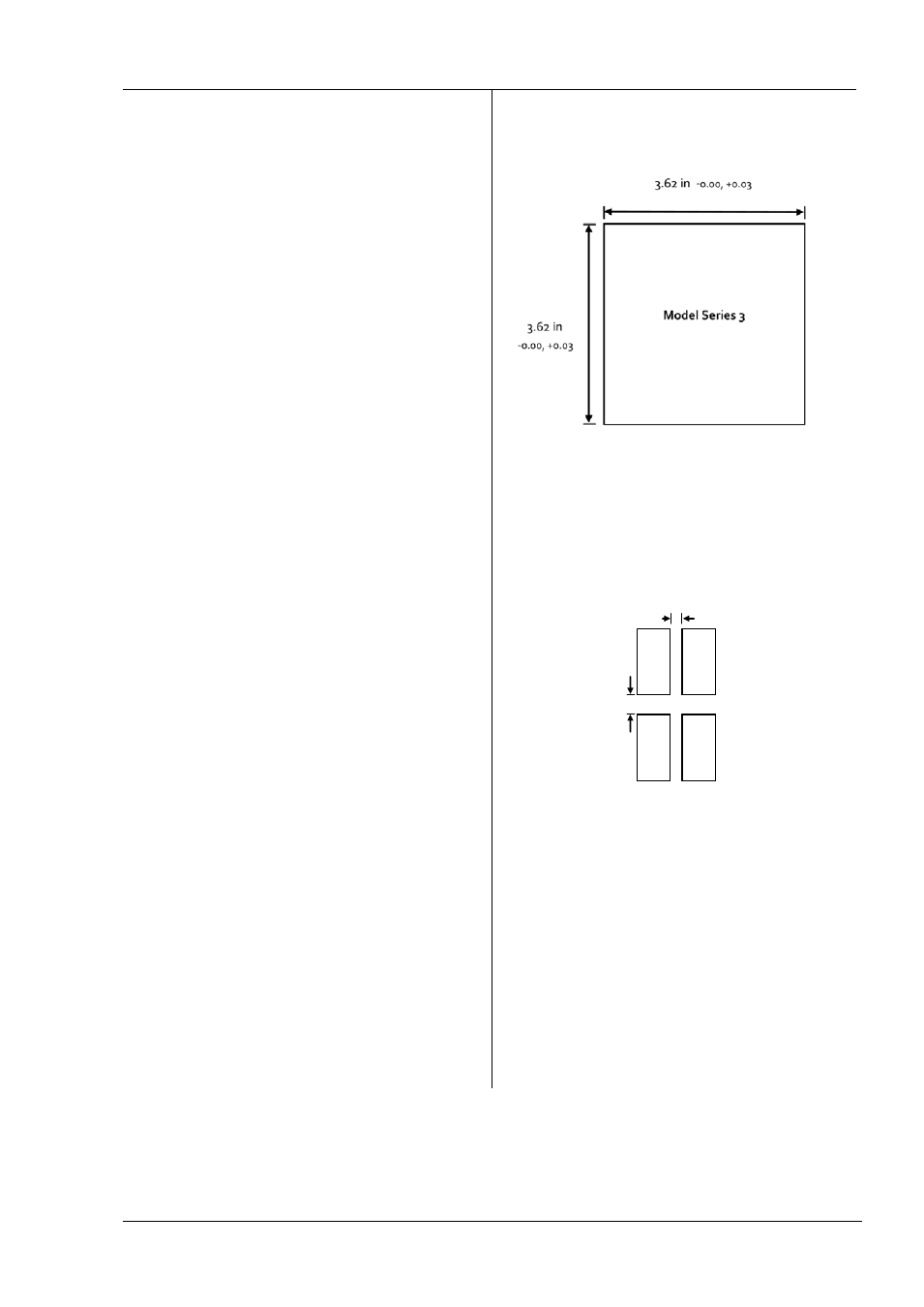
1.3.2
Panel Cut Out Sizes
1.3.3
Recommended minimum spacing of
controllers
1.3.4
To Remove the Controller from its Sleeve
The controller can be unplugged from its sleeve by easing
the latching ears outwards and pulling it forward out of the
sleeve. When plugging it back into its sleeve, ensure that
the latching ears click back into place to maintain the sealing
10mm (0.4 in)
38mm (1.5 in)
(Not to scale)