Channel bonding, Channel bonding -5 – Altera JESD204B IP User Manual
Page 10
F Parameter
This parameter indicates how many octets per frame per lane that the JESD204B link is operating in. You
must set the F parameter according to the JESD204B IP Specification for a correct data mapping.
To support the High Density (HD) data format, the JESD204B IP core tracks the start of frame and end of
frame because F can be either an odd or even number. The start of frame and start of multi-frame wrap
around the 32-bits data width architecture. The RX IP core outputs the start of frame (
sof[3:0]
) and
start of multiframe (
somf[3:0]
), which act as markers, using the Avalon-ST data stream. Based on these
markers, the transport layer build the frames.
In a simpler system where the HD data format is set to 0, the F will always be 1, 2, 4, 6, 8, and so forth.
This simplifies the transport layer design, so you do not need to use the
sof[3:0]
and
somf[3:0]
markers.
Channel Bonding
The JESD204B IP core supports channel bonding—bonded and non-bonded modes.
The channel bonding mode that you select may contribute to the transmitter channel-to-channel skew. A
bonded transmitter datapath clocking provides low channel-to-channel skew as compared to non-bonded
channel configurations.
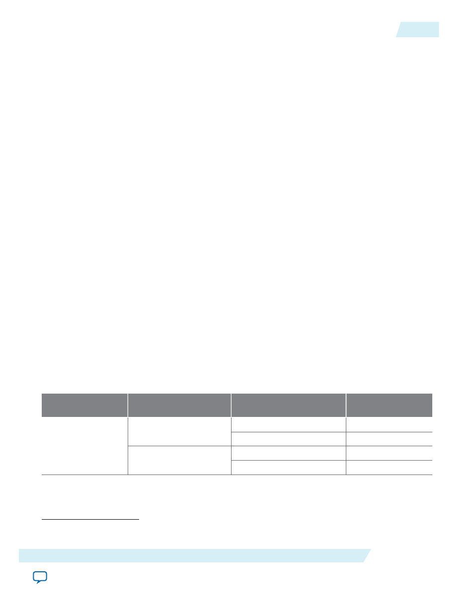
Table 2-2: Maximum Number of Lanes (L) Supported in Bonded and Non-Bonded Mode
• In PHY-only mode, you can generate up to 32 channels, provided that the channels are on the same side. In
MAC and PHY integrated mode, you can generate up to 8 channels.
• In bonded channel configuration, the lower transceiver clock skew and equal latency in the transmitter phase
compensation FIFO for all channels result in a lower channel-to-channel skew. You must use adjacent
channels when you select ×6 bonding. You must also place logical channel 0 in either physical channel 1 or 4.
Physical channels 1 and 4 are indirect drivers of the ×6 clock network. The JESD204B IP core automatically
selects between xN or feedback compensation (fb_compensation) bonding depending on the number of
transceiver channels you set.
• When you select bonded channel and L<6, the IP core automatically selects xN/x6 bonding mode for the
transceiver. When you select bonded channel and L≥6, the IP core automatically selects x6 PLL fb_compensa‐
tion bonding mode for the transceiver
• In non-bonded channel configuration, the transceiver clock skew is higher and latency is unequal in the
transmitter phase compensation FIFO for each channel. This may result in a higher channel-to-channel skew.
Device Family
Core Variation
Bonding Mode Configuration
Maximum Number of
Lanes (L)
Arria V
PHY only
Bonded
32
(2)
Non-bonded
32
(2)
MAC and PHY
Bonded
6
Non-bonded
8
(2)
The maximum lanes listed here is for configuration simplicity. Refer to the Altera Transceiver PHY User
Guide for the actual number of channels supported.
UG-01142
2015.05.04
Channel Bonding
2-5
About the JESD204B IP Core
Altera Corporation