Figure 6-2, The latest arrival lane variation falls – Altera JESD204B IP User Manual
Page 141
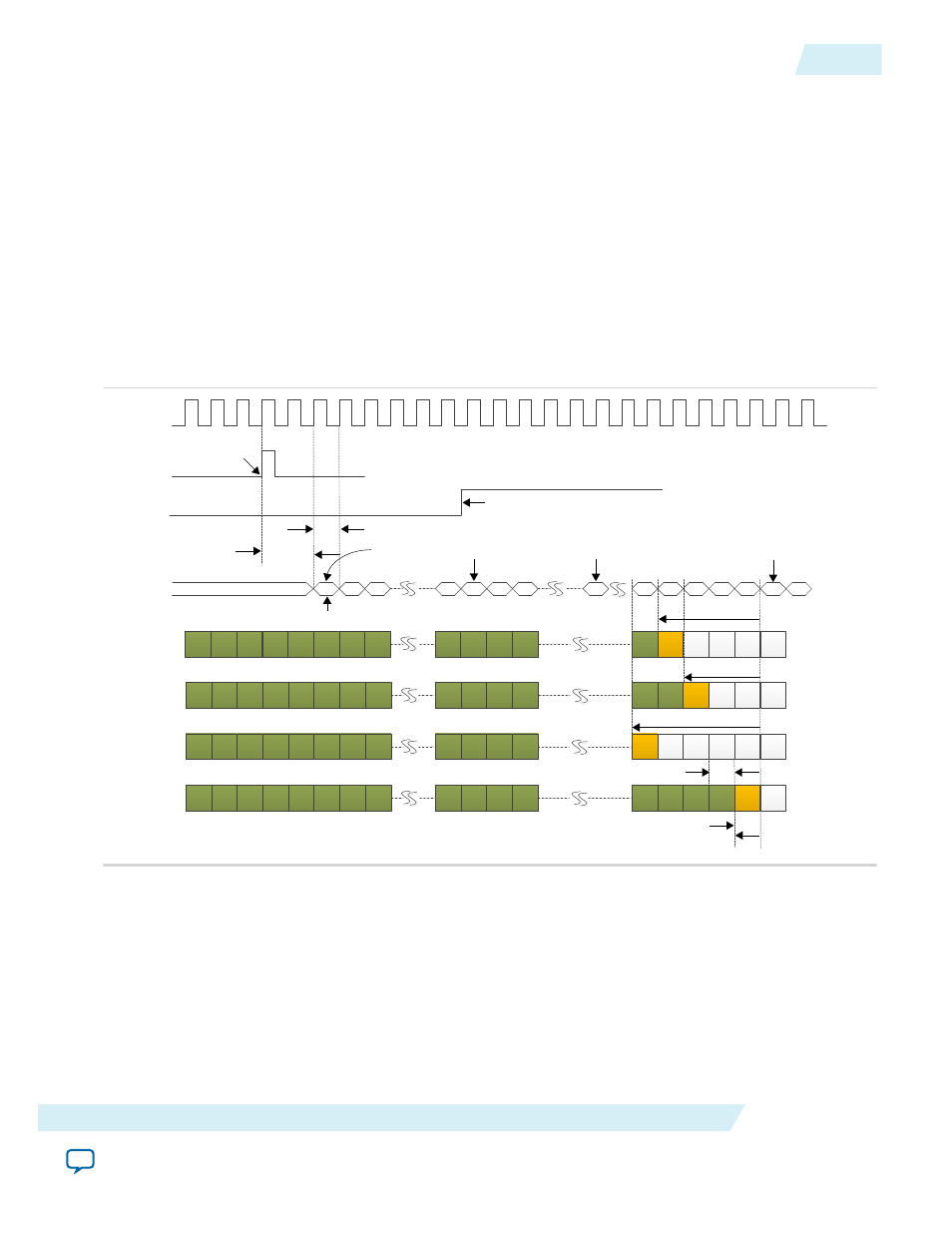
Figure 6-2: Early RBD Release Opportunity for Latest Arrival Lane Within One Local Multi-Frame
Scenario
In this example, the SYSREF pulse at rx_sysref port of the IP core is sampled by the internal register. After
2 link clock cycles, the LMFC counter resets. The delay from SYSREF sampled high to LMFC counter
resets is deterministic. The transition of /K/ character to /R/ character marks the beginning of ILAS phase.
The number of LMFC count of the /R/ character relative to the next LMFC boundary in the latest arrival
lane is reported as the RBD count. In the first power cycle, the /R/ character is received at 4 LMFC counts
before the next LMFC boundary, hence the RBD count = 4. In the second power cycle, the /R/ character is
received at 3 LMFC counts before next LMFC boundary, hence the RBD count = 3. In five power cycles,
the RBD count varies from 3 to 5. Since there are limited number of power cycles and boards for
characterization, 1 LMFC count tolerance is allocated as a guide to set early RBD release opportunity.
Hence, setting csr_rbd_offset = 1 can safely release the elastic buffer 1 LMFC count earlier at LMFC count
7 before the next LMFC boundary. If the RBD elastic buffer is released before the latest arrival lane, this
will cause a lane de-skew error.
1st LMFC boundary
SYSREF pulse is
sampled by IP core
internal register
2 link clock cycle deterministic
delay from SYSREF sampled
high to 1stLMFC boundary
Link clock
Free running LMFC counter
Internal
LMFC Counter
0
1
2
7
0
1
2
3
4
5
6
7
K
SYNC_N deasserted
at LMFC boundary
K
K
R
K
K
K
K
K
Latest arrival
lane in first
power cycle
D
D
D
D
K
K
0
1
RBD count = 4
K
K
K
K
K
K
K
K
K
Latest arrival
lane in second
power cycle
R
D
D
D
K
K
RBD count = 3
K
K
K
D
K
K
K
K
K
Latest arrival
lane in fifth
power cycle
D
D
D
D
K
R
4thLMFC boundary
RBD count = 5
K
K
K
K
K
K
K
K
K
Aligned
outputs on all
lanes
K
K
R
D
K
K
1 link clock or LMFC
count to cater for
power cycle variation
RBD Elastic Buffers
Released
Set csr_rbd_offset = 1
1 link clock period = LMFC count
4 LMFC counts from
LMFC boundary
Internal LMFC counter resets
SYNC_N
rx_sysref
2ndLMFC boundary
K
K
K
K
K
K
K
K
K
K
K
K
0
3rd LMFC boundary
UG-01142
2015.05.04
Programmable RBD Offset
6-3
JESD204B IP Core Deterministic Latency Implementation Guidelines
Altera Corporation