Altera JESD204B IP User Manual
Page 147
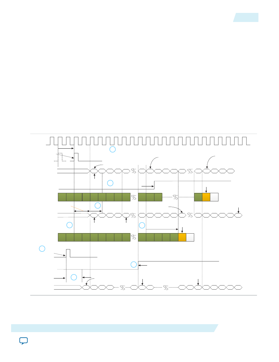
The SYSREF pipeline registers in the FPGA introduce additional latency to SYSREF when detected by the
IP core. Therefore, you can use TX LMFC offset to reduce or eliminate this additional latency. The next
figure illustrates the technique of optimizing latency using TX LMFC offset.
Figure 6-8: Optimizing IP Core Latency Using TX LMFC Offset
Sequence of events in the diagram:
1. The DAC samples the SYSREF pulse.
2. The DAC's internal LMFC counter resets after a deterministic delay.
3. The SYSREF pipeline registers introduces an additional 2 link clock latency.
4. The csr_lmfc_offset field is set to 4. The IP core internal LMFC counter resets after 2 link clock cycles.
5. The LMFC boundary is delayed by 4 link clock.
6. The DAC deasserts SYNC_N at the LMFC boundary.
7. SYNC_N deassertion is detected by the JESD204B IP core.
8. Because LMFC boundary is delayed by 4 link clock, the IP core detects the SYNC_N deassertion before
the second LMFC boundary. ILAS transmission begins at the second LMFC boundary instead of the
third LMFC boundary (in
). The latency is shortened by 4 LMFC counts or link clock cycles.
1
2
3
4
5
6
7
8
First LMFC
boundary
SYSREF pulse is
sampled by DAC
2 link clock cycle deterministic
delay from SYSREF sampled
high to LMFC counter resets
Free running LMFC counter
Internal
LMFC Counter
0
1
7
0
1
0
1
2
3
4
5
SYNC_N deasserted
at the LMFC boundary
7
Third LMFC
boundary
Free running LMFC counter
0
1
2
3
7
0
1
2
3
SYSREF pulse is
sampled by FPGA
IP core
SYNC_N transmitted by DAC
0
SYNC_N deassertion is
detected by IP core
SYNC_N
arrival at TX
K
K
K
K
R
K
K
K
K
K
L Transmit
lanes
D
ILAS transmission by FPGA
Internal LMFC counter resets
csr_lmfc_offset=0
First LMFC
boundary
Second LMFC boundary
at new location
Third LMFC
boundary
6
Link clock
Internal
LMFC Counter
Deterministic delay
from SYSREF sampled
high to the first LMFC
boundary
Free running LMFC counter
4
5
6
7
4
5
6
7
Internal
LMFC Counter
Internal LMFC counter resets
csr_lmfc_offset=4
First LMFC boundary
at new location
K
K
K
K
R
K
K
K
K
K
L Transmit
lanes
K
K
LMFC boundary is
delayed by 4 link clocks
Additional 2 link clock latency
caused by SYSREF pipeline registers
K
K
6
5
4
3
Second LMFC
boundary
tx_sysref
LMFC boundary is
delayed by 4 link clocks
Second LMFC
boundary
2
3
1
ILAS transmission by FPGA
7
2
7
3
D
3
4
0
K
4
0
0
Third LMFC boundary at
new location
K
K
K
K
The csr_lmfc_offset field provides a convenient way to achieve deterministic latency and potentially
optimizing the IP core latency. There are other ways that you can achieve deterministic latency by using
the features available at the converters. Consult the converter manufacturer for details of these features.
UG-01142
2015.05.04
Programmable LMFC Offset
6-9
JESD204B IP Core Deterministic Latency Implementation Guidelines
Altera Corporation