System parameters, System parameters -40 – Altera JESD204B IP User Manual
Page 121
System Parameters
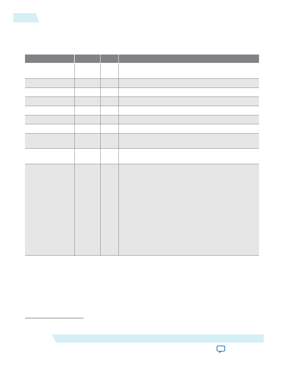
Table 5-18: System Parameter Settings
This table lists the parameters exposed at the system level.
Parameter
Value
(37)
Default
Description
LINK
1, 2
1
Number of JESD204B link. One link represent one JESD204B
instance.
L
1, 2, 4, 8
2
Number of lanes per converter device.
M
1, 2, 4, 8
2
Number of converters per device.
F
1, 2, 4, 8
2
Number of octets per frame.
S
1, 2
1
Number of transmitted samples per converter per frame.
N
12–16
16
Number of conversion bits per converter.
N'
16
16
Number of transmitted bits per sample in the user data format.
F1_FRAMECLK_
DIV
1, 4
4
The divider ratio on
frame_clk
when F = 1. The transport
layer uses the post-divided
frame_clk
.
F2_FRAMECLK_
DIV
1, 2
2
The divider ratio on
frame_clk
when F = 2. The transport
layer uses the post-divided
frame_clk
.
POLYNOMIAL_
LENGTH
7, 9, 15, 23,
31
7
Defines the polynomial length for the PRBS pattern generator
and checker, which is also the equivalent number of stages for
the shift register.
• If PRBS-7 is required, set this parameter to 7.
• If PRBS-9 is required, set this parameter to 9.
• If PRBS-15 is required, set this parameter to 15.
• If PRBS-23 is required, set this parameter to 23.
• If PRBS-31 is required, set this parameter to 31.
This parameter value must not be larger than N, which is the
output data width of the PRBS pattern generator or converter
resolution. If an N of 12-14 is required, PRBS-7 and PRBS-9 are
the only feasible options. If an N of 15-16 is required, PRBS-7,
PRBS-9, and PRBS-15 are the only feasible options.
(37)
Values supported or demonstrated by this design example.
5-40
System Parameters
UG-01142
2015.05.04
Altera Corporation
JESD204B IP Core Design Guidelines