Altera JESD204B IP User Manual
Page 153
Transport Layer
Verify the RX transport layer operation using these signals in the altera_jesd204_transport_rx_top.sv:
• jesd204_rx_dataout
• jesd204_rx_data_valid
• jesd204_rx_data_ready
• jesd204_rx_link_data_ready
• jesd204_rx_link_error
• rxframe_rst_n
Use the
rxframe_clk
signal as the sampling clock.
For normal operation, the
jesd204_rx_data_valid
,
jesd204_rx_data_ready
, and
jesd204_rx_link_data_ready
signals should be asserted while the
jesd204_rx_link_error
should be
deasserted. You can view the ramp or sine wave test pattern on the
jesd204_rx_dataout
bus.
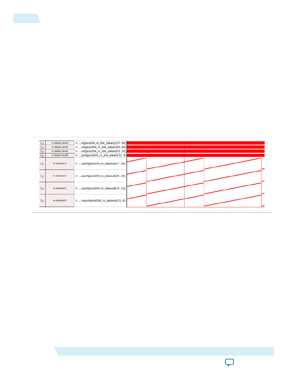
Figure 7-2: Ramp Pattern on the
jesd204_rx_dataout
Bus
This is a SignalTap II image during the JESD204B user data phase with ramp pattern transmitted from the
ADC.
Verify the TX transport layer operation using these signals in the altera_jesd204_transport_tx_top.sv:
• txframe_rst_n
• jesd204_tx_datain
• jesd204_tx_data_valid
• jesd204_tx_data_ready
• jesd204_tx_link_early_ready
• jesd204_tx_link_data_valid
• jesd204_tx_link_error
Use the
txframe_clk
signal as the sampling clock.
For normal operation, the
jesd204_tx_data_valid
,
jesd204_tx_data_ready
,
jesd204_tx_link_early_ready
, and
jesd204_tx_link_data_valid
signals should be asserted while
the
jesd204_tx_link_error
should be deasserted. You can verify the user data arrangement (shown in
the data mapping tables in the
on page 5-18) by referring to the
jesd204_tx_datain
bus.
7-6
Debugging JESD204B Link Using SignalTap II and System Console
UG-01142
2015.05.04
Altera Corporation
JESD204B IP Core Debug Guidelines