Programmable rbd offset, Programmable rbd offset -2 – Altera JESD204B IP User Manual
Page 140
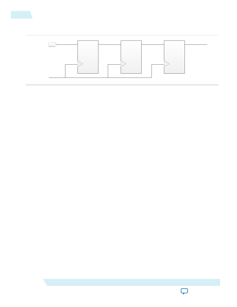
Figure 6-1: Multi-Stage Pipeline Register for SYSREF Signal
Figure shows a two stages pipeline registers for the SYSREF signal.
SYSREF at
FPGA pin
D
Q
D
Q
D
Q
User logic:
1
st
stage
pipeline
register
User logic:
2
nd
stage
pipeline
register
To IP core
internal logic
IP core register
rxlink_clk or
txlink_clk
Programmable RBD Offset
In the RX IP core, the programmable RBD offset provides flexibility for an early RBD release to optimize
the latency through the IP core. You can configure the RBD offset using the csr_rbd_offset field in the
syncn_sysref_ctrl
register.
You should set a safe RBD offset value to ensure deterministic latency from one power cycle to another
power cycle. Follow these steps to set a safe RBD offset value:
1. Read the RBD count from the csr_rbd_count field in
rx_status0
register. Record the value.
2. Power cycle the JESD204B subsystem, which consists of the FPGA and converter devices.
3. Read the RBD count again and record the value.
4. Repeat steps 1 to 3 at least 5 times and record the RBD count values.
5. Set the csr_rbd_offset accordingly with one LMFC count tolerance.
6. Perform multiple power cycles and make sure lane de-skew error does not occur using this RBD offset
value.
The RBD count should be fairly consistent, within 2 counts variation from one power cycle to another
power cycle. In the following examples, the parameter values are L > 1, F=1 and K=32. The legal values of
the LMFC counter is 0 to ((FxK/4)-1), which is 0 to 7. In
, the latest arrival lane variation falls
within 1 local multi-frame period. In this scenario, if latency is not a concern, you can leave the default
value of csr_rbd_offset=0, which means the RBD elastic buffer is released at the LMFC boundary. In
, the latest arrival lane variation spans across 2 local multi-frames; the latest arrival lane
variation happens before and after the LMFC boundary. In this scenario, you need to configure the RBD
offset correctly to avoid lane de-skew error as indicated in bit 4 of
rx_err0
register.
6-2
Programmable RBD Offset
UG-01142
2015.05.04
Altera Corporation
JESD204B IP Core Deterministic Latency Implementation Guidelines