Analog input parameters – GAI-Tronics Sonic Alarm Sonic Alarm System Software Programming and User Manual User Manual
Page 27
Pub. 42004-410A
Sonic Alarm™ System Programming and User Manual
Page: 24 of 98
f:\standard ioms - current release\42004 instr. manuals\42004-410a.doc
03/09
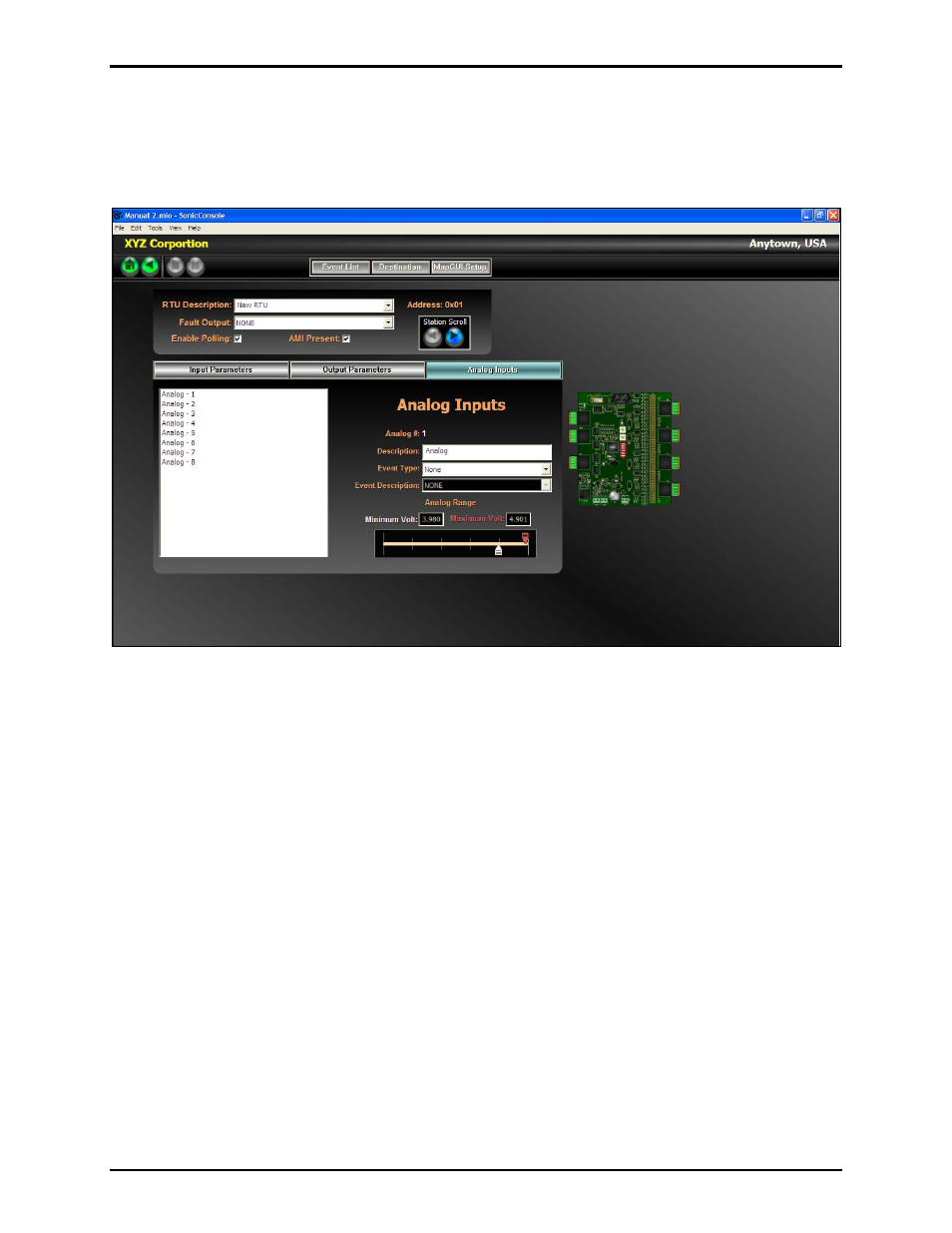
Analog Input Parameters
Each RTU monitors up to eight analog voltage inputs from 0 to +5 V dc. Each input is individually
programmed to activate if the measured voltage is outside a pre-programmed range. A resistor voltage
divider must be installed if the voltages to be monitored are greater than 5 V dc.
Selecting the Analog Input Number – Select the input number (1–8) to be programmed by clicking on it
in the table left side of the screen. When selected, the parameters are displayed on the right side of
screen. It is possible to navigate through the inputs by using the up and down arrows on keyboard.
Description – A text description of how the input point is being used (e.g. low battery voltage, etc.)
Event Type – From the pull-down list, select the type of event that will be activated from the input.
Event Description -
From the pull-down list, select the event that will be activated from the input.
N
OTE
: If the events have not yet been defined, the list will be blank. Events must first be defined on the
Event List screen.
Analog Range - Use the slide bars to define the normal operating voltage range. The white pointer sets
the minimum voltage threshold and the red pointer sets the maximum voltage threshold. If the analog
voltage being monitored is outside of these levels, the input’s assigned event will become active.