Event, Figure 104: ethernet port configuration – NavCom SF-3050 Rev.I User Manual
Page 109
SF-3050 GNSS Product User Guide
– Rev I
90
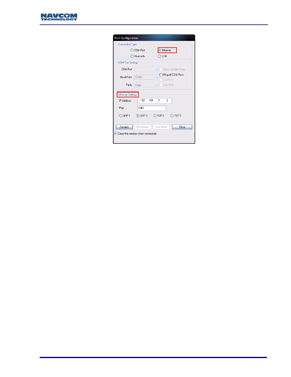
Figure 104: Ethernet Port Configuration
4. Click the Connect button.
5. Verify that the SF-3050 is connected to the PC. Messages scrolling in the
Communication window indicate that the connection is established (see Figure 5).
If an Ethernet connection is not established, use StarUtil 3000 to verify the
IP address of the SF-3050. A serial connection must be used to determine
the
receiver’s IP address.
Event
The SF-3050 accepts an event input pulse to synchronize external incidents requiring
precise GNSS time tagging, such as aerial photography. For example, the action of a
camera’s shutter creates an input pulse to the Event port. The SF-3050M outputs position
and time information relative to each event received.
The Event is input on Pin 3 of the 9-pin male Positronic connector power port on the rear
of the sensor (refer to Table 7).
Specifications:
Selectable Input Voltage, 5V or 12V
Minimum pulse width, 100nS
Rising or Falling edge Synchronization
Detailed specifications of the Event Input, cable wiring, and configuration
may be found in Appendix D of this User Guide.