Connect equipment, Figure 1: sf-3050 rear view – NavCom SF-3050 Rev.I User Manual
Page 21
SF-3050 GNSS Product User Guide
– Rev I
2
Profile. If desired, replace the factory default user profile with a predefined profile, or
create a profile. Predefined User Profiles are available on the USB Flash Drive or by
email.
Refer to Chapter 5/User Profiles for details.
Connect Equipment
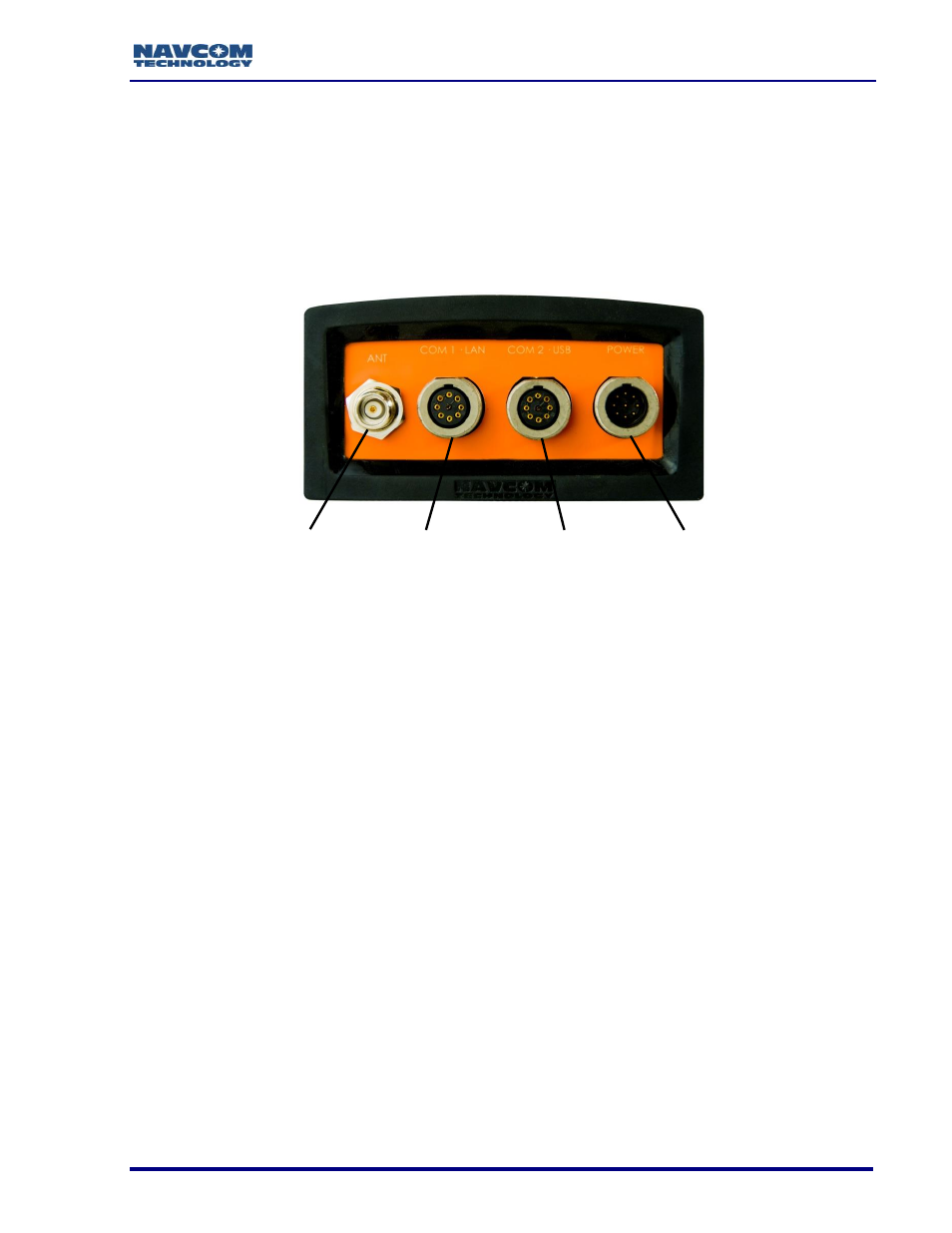
Figure 1: SF-3050 Rear View
Refer to Figure 1 for the steps below:
1. Use one of the two supplied data cables for communications:
DB9S cable (P/N 94-310260-3006LF): Connect the Positronic connector end to
COM2 - USB at the rear of the SF-3050. Connect the DB9S end to the PC.
Or
USB 2.0 Device cable (P/N 94-310266-3006LF): Connect the Positronic connector
end to COM2 - USB at the rear of SF-3050. Plug the USB plug end into the PC.
, Communication Ports, for details on the ports and Bluetooth
connection.
2. Mount the supplied Rover, Base, or Airborne antenna. Locate the antenna in an area
with a 360
clear view of the sky.
Refer to Chapter 4/Antennae for additional considerations and restrictions.
3. Connect the supplied GNSS antenna cable
(P/N 94-310261-3012LF) to the GNSS antenna. Connect the other end of the cable to
the TNC connector, labeled ANT, at the rear of the SF-3050.
ANTENNA
COM1 - LAN
POWER
COM2 - USB