Gnss antenna connector, Figure 109: communication port connections, Table 21 – NavCom SF-3050 Rev.I User Manual
Page 115
SF-3050 GNSS Product User Guide
– Rev I
96
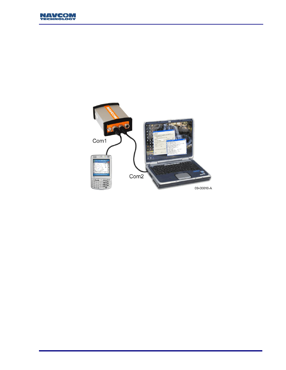
Figure 109 shows a common configuration with the control device
connected to COM1 - LAN and an auxiliary device connected to
COM2 - USB for data logging.
Some devices may require an additional adapter. The optional interface
data cables support USB 2.0 Device and Host, Ethernet, and RS-232 and
RS-422 (refer to Table 13). The receiver is configured as a DCE device.
Figure 109: Communication Port Connections
GNSS Antenna Connector
The connector used on the SF-3050 is a TNC female, labeled ANT on the rear panel of
the sensor as shown in Figure 83.
The GNSS antenna connector provides +5V
0.5V at 100mA. Do not
disconnect the antenna when the GNSS unit is powered on.
The system is supplied with 12ft (3.6m) of RG58/U cable (P/N 94-310261-
3012LF). The cable is fitted with two straight male TNC connectors.
The cable length between the antenna and SF-3050 should not exceed 7dB loss at
1.575GHz for optimum performance, though the system may tolerate up to 10dB of cable
loss with minimal performance. Lower elevation satellite tracking suffers the most with
more than 7dB insertion loss.