14 orientation speed (sort : c2-11 and c3-11), 14 orientation speed (s – Yaskawa Varispeed 626M5 User Manual
Page 120
Trial Operation
6.4.14 Orientation Speed (S
ORT
: C2-11 and C3-11)
6 -14
6.4.14 Orientation Speed (S
ORT
: C2-11 and C3-11)
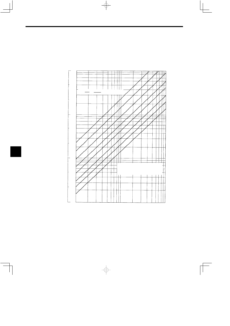
Make sure the Motor has stopped before setting the orientation speed.
The orientation speed settings are determined by the moment of inertia (including the Motor shaft), and
the torque. Consequently, calculate the load shaft moment of inertia and the load shaft torque when using
the H gear for each machine separately, and then determine the orientation speed by referring to the dia-
gram below. This speed is the upper limit, so the orientation speed can be set to a lower value than this one.
Formula
Load torque (Ts)
Note: Convert the load shaft torque us-
ing the gear ratio (load shaft/Motor
shaft) of the Motor continuous rated
torque.
(kgf S m
2
) (kg S m
2
)
40
10
30 min
−1
60 min
−1
100 min
−1
150 min
−1
200 min
−1
300 min
−1
400 min
−1
600 min
−1
GD
2
11
4
2
0.4
0.2
1
0.1
0.04
0.01
0.1
1
J =
×
(Kp: Position loop gain 10)
60
2π
T
Kp−N
10
100
1000 (N S m)
Load
shaft
moment
of
inertia
Fig 6.10
Orientation Speed Settings
6