1 inverter operating status, Operating status displays – Yaskawa Varispeed 626M5 User Manual
Page 182
Operating Status Displays
11 -2
11.1 Inverter Operating Status
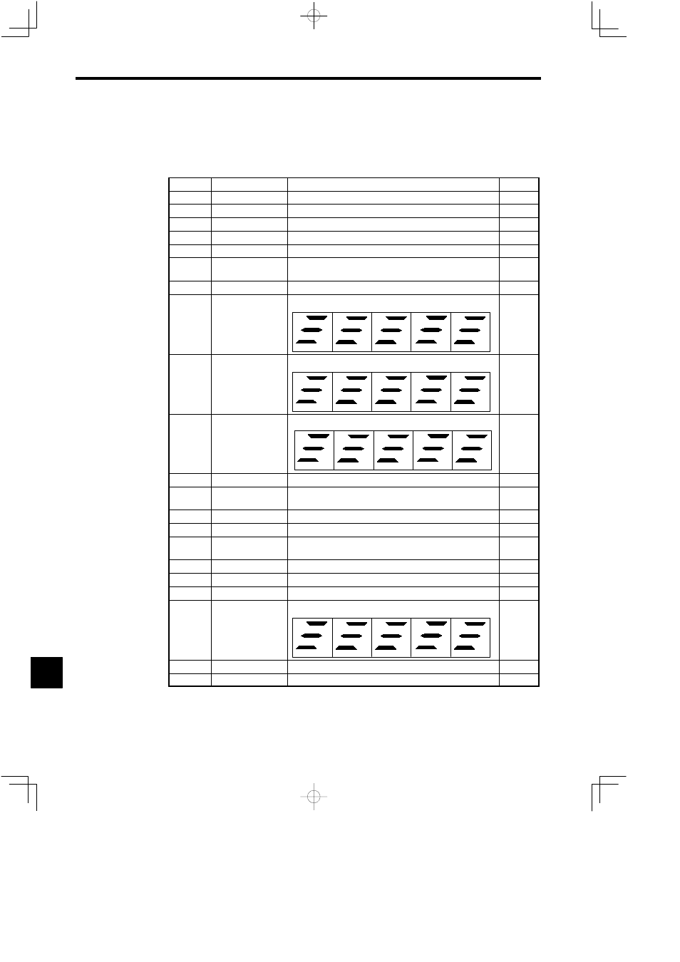
The status displays when the Inverter is operating are listed in the following table.
Table 11.1
Operating Status Displays for Inverter Operation
No.
Signal Name
Explanation
Unit
U1-01
Motor speed
Speed detected by the motor encoder
min
−1
U1-02
Speed reference
Speed control reference. Percentage of the rated speed (C1-26)
%
U1-03
Load shaft speed
Product of motor speed and gear transmission ratio
min
−1
U1-04
Torque reference
Percentage of 30-minute rating (100%)
%
U1-05
−−−
−−−−−−−−
U1-06
Inverter output cur-
rent
Detected Inverter output current converted to amperes.
Accuracy: ±3%
A
U1-07
Output frequency
Inverter output current frequency
Hz
U1-08
*1
Internal status
Operating status signal (at logical level)
IRDY
BB
EMGL
RGM
ESP0
RST
YNALM
RUN
PUVSTS
CLIM
MD
CONFLT
CONRDY
INTMY
INTMC
U1-09
Input signal status
Sequence input signal ON/OFF status
*2
RDY
TLL
EMG
SSC
FWD
RST
REV
CHW
TLH
PPI
ORT
LGR
MGR
DAS
(CHWA)
U1-10
Output signal status
Sequence output signal ON/OFF status
*2
ZSPD
ORG
AGR
ORE
SDET
CHWE
TDET
FLT
TLE
TALM
FC0
FC1
FC2
FC3
FLTL
U1-11
Inverter capacity
Inverter unit 30-minute rated capacity
kW
U1-12
Inverter internal
temperature
Detected Inverter internal temperature (control PC board)
°C
U1-13
Heatsink temperature
Detected heatsink temperature of Inverter. Accuracy: ±5°C (±41°F)
°C
U1-14
*1
DC bus voltage
Main circuit capacitor voltage
V
U1-15
*1
Analog speed refer-
ence A/D converter
Conversion value of analog reference used to adjust the speed refer-
ence offset.
U1-16
−−−
−−−−−−−−
U1-17
*1
Phase-U current
Detected phase-U current converted from analog to digital
U1-18
*1
Phase-W current
Detected phase-W current converted from analog to digital
U1-19
*3
12-bit digital refer-
ence signal status
On/OFF status of 12-bit digital reference signal.
*2
D1
D6
D2
D7
D3
D8
D4
D9
D5
D10
D11
D12
U1-20
LED check
All LEDs on the Digital Operator light when U1-20 is selected.
U1-21
PROM No.
PROM software version number is displayed (lower 5 digits).
* 1. Operating status display data for in-house adjustment.
* 2. The LED segments for ON I/O signals will light.
* 3. Operating status display is enabled for independent drives (M5A) only.
11