Yaskawa Varispeed 626M5 User Manual
Page 71
3.4 Wiring Control Circuit Signals
3 -31
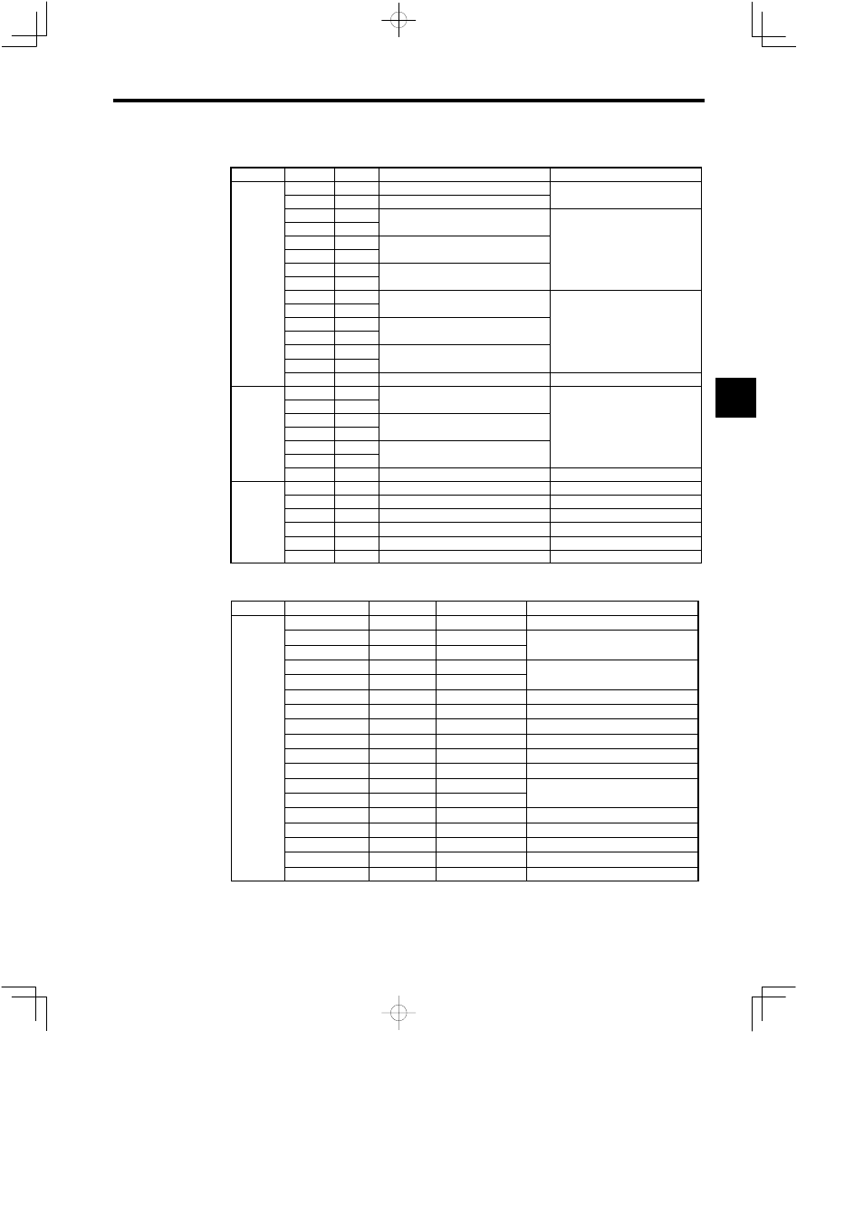
Table 3.14
Control Circuit Signals (8CN, 9CN, 10CN)
Connector
Signal
No.
Function
Signal Level
+5V
4, 5, 6
+5V power supply for encoder
+5V
0V
1, 2, 3
Encoder power supply 0 V
+5V
Load current: 350mA or less
CPA
9
*CPA
11
−
RS 422A specification
CPB
12
RS-422A specification
Line receiver
*CPB
13
−
Line receiver
+5 V
8CN
CPC
7
+5 V
8CN
(option)
*CPC
8
−
(option)
SPA
16
Encoder phase A signal input
*SPA
17
Encoder phase A signal input
RS-422A specification
SPB
18
Encoder phase B signal input
RS-422A specification
Line receiver
*SPB
19
Encoder phase B signal input
Line receiver
+5 V
SPC
14
Encoder phase C signal input
+5 V
*SPC
15
Encoder phase C signal input
SS
20
Shield (0V)
−
SPAO
4
Encoder phase A signal output
*SPAO
5
Encoder phase A signal output
RS-422A specification
9CN
SPBO
6
Encoder phase B signal output
RS-422A specification
Line driver
9CN
(option)
*SPBO
7
Encoder phase B signal output
Line driver
+5 V
(option)
SPCO
2
Encoder phase C signal output
+5 V
*SPCO
3
Encoder phase C signal output
SS
1
Shield (0V)
−
SIG+
13
Magnetic sensor signal +
−
SIG−
14
Magnetic sensor signal −
−
10CN
+15V
12
+15V power supply for magnetic sensor
+15V Load current: 100mA or less
10CN
(option)
+12V
10
+12V power supply for magnetic sensor
+12V Load current: 50mA or less
(option)
0V
3, 5
Magnetic sensor power supply 0V
−
SS
1
Shield (0V)
−
Table 3.15
Control Circuit Signals (51CN, 52CN, 5CN)
Connector
Signal
No. (51CN)
No. (52CN, 5CN)
Function
0V
1, 2
1, 2
0V
BAT−
3
4
BAT+
5
6
−
S
4
3
*S
6
5
−
0V
7 to 14
7 to 14
0V
+24V
*1
15 to 22
15 to 22
+24V power supply
51CN
AXRUN
23
24
Inverter (servo) running
51CN
52CN
CONRST
24
23
Fault reset
52CN
5CN
CONRDY
25
26
Converter ready
5CN
CONFLT
26
25
Converter fault
ALM±
*2
29
30
Inverter (servo) fault
ALMC
*2
27
28
Inverter (servo) fault
ESP0
*2
31
32
Inverter emergency stop
ESP1
28
27
−
/EXT2
30
29
−
/EXT1
32
31
−
+24VIN
*2
34
33
+24V power supply input
* 1. The 24 V power supply is output only for M5N models for NC systems.
* 2. These signals are used only for M5N models for NC systems.
3