Yaskawa Varispeed 626M5 User Manual
Page 144
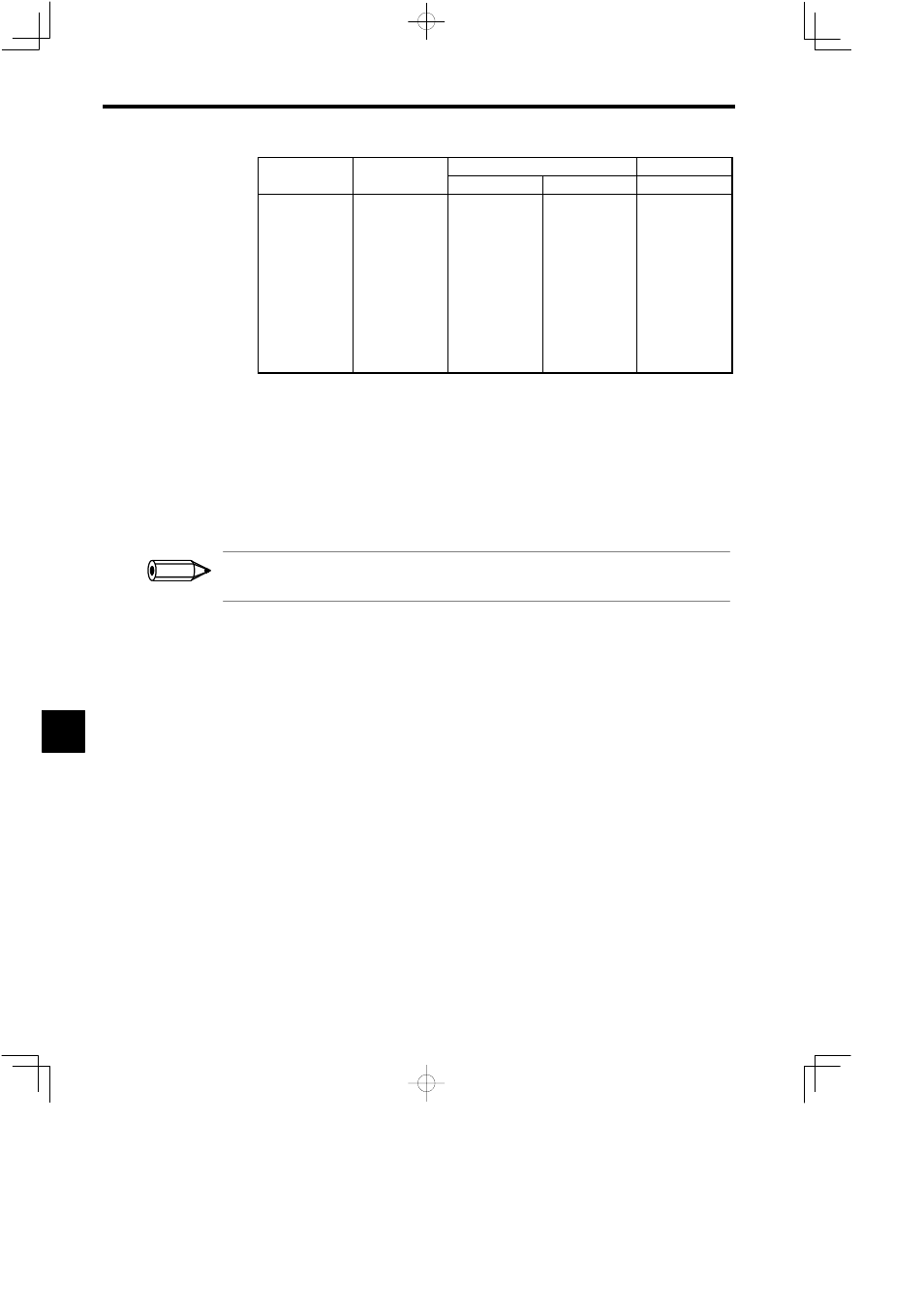
Orientation Control Using an Encoder
8.7.3 Details of the Stop Position Reference Signal
8-10
Signal
Pin Number
Binary
BCD
Without Sign
With Sign
With Sign
D1
D2
D3
D4
D5
D6
D7
D8
D9
D10
D11
D12
19
20
21
22
23
24
25
26
27
28
29
30
1
2
4
8
16
32
64
128
256
512
1024
2048
1
2
4
8
16
32
64
128
256
512
1024
Sign
1
2
4
8
10
20
40
80
100
200
400
Sign
D
When using signed binary data, the meaning of the signal will depend on the sign (+ or −).
If the sign is positive, the total number of bit pulses input is added:
0 0 1 0 1 0 0 1 0 0 1
:
:
:
:
256+ 64
+
8
+
1 = 329
If the sign is negative, the negative of sum of the number of bit pulses input is used:
− (256 + 64 + 3 + 1) = −329
D
For incremental operations, binary references cannot be above 180_. For BCD references, references
above 180_ are possible depending on the setting of the BCD stop position reference resolution C2-12
(P
BCD
) to a maximum of ±360_.
The input signal circuit for the stop position reference for the Encoder orientation is the same as that shown
in 3.4.4 Sequence Input Signal Circuits.
8
INFO