7 magnet and magnetic sensor mountings, Mounting diagram, Mounting dimensions – Yaskawa Varispeed 626M5 User Manual
Page 159
Magnetic Sensor Orientation Control
9 -10
9.7
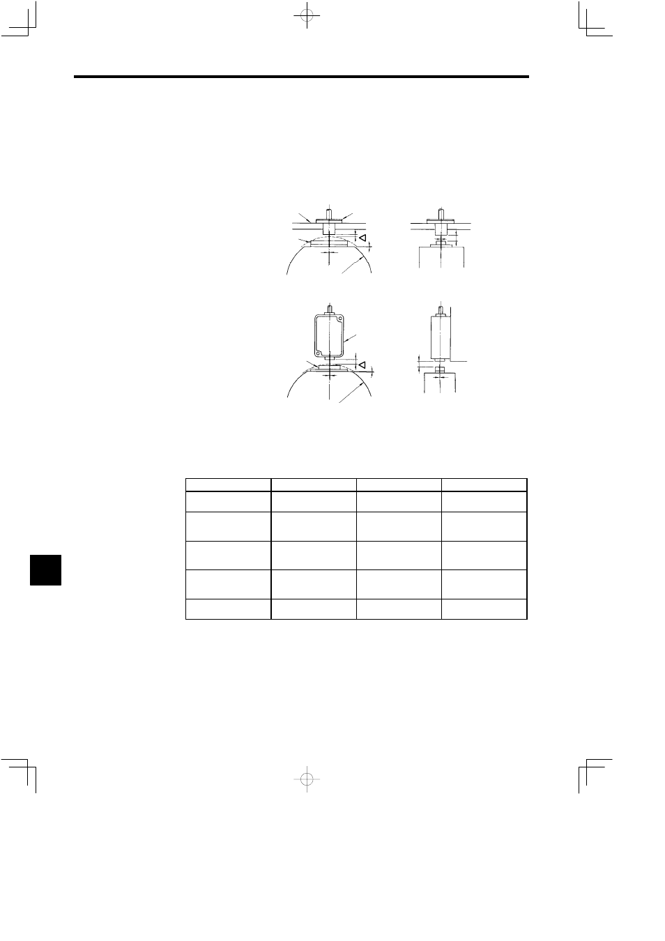
Magnet and Magnetic Sensor Mountings
The Magnet is mounted directly to the load shaft as shown in the following diagram. The Magnetic Sensor is
mounted to a part of the load shaft that does not rotate, but must be mounted so that the positioning of the center
of the Magnet agrees exactly with the center of the Magnetic Sensor.
J
Mounting Diagram
Mounting panel
(panel width 8 mm max.)
MG-1378BS Magnet
FSH-1378C
Magnetic Sensor
(a) MG-1378BS/FS-1378C
MG-1444S Magnet
FS-200A Magnetic Sensor
Magnetic Sensor
mounting panel
(b) MG-1444S/FS-200A
L
n
S
1
R
δ
n
S
2
L
L
n
S
1
R
δ
n
S
2
L
Fig 9.12
Magnet and Magnetic Sensor Mounting Diagram 1
J
Mounting Dimensions
The mounting dimensions for the above diagram are shown in the following table.
Sign
Name
MG-1378BS/FS-1378C
MG-1444S/FS-200A
R
Radius of rotating part
mounted to the Magnet
*1
60 to 70 mm
60 to 70 mm
L
Gap (between center of
Magnet and Magnetic
Sensor)
*2
6 mm (6 to 8 mm)
5 mm (3 to 7 mm)
∆L
Gap (between tip of Mag-
net and Magnetic Sen-
sor)
*2
1 to 2 mm
1 to 2 mm
∆S
1
and ∆S
2
Magnet and center of
Magnetic Sensor are no
longer aligned.
*3
0.5 mm max.
0.5 mm max.
δ
Angle of misalignment
from base surface.
*3
0.2_ max.
0.2_ max.
* 1.
When specifying the radius of the rotating part mounted to the Magnet, consider the maxi-
mum speed tolerance of the Magnet.
* 2.
The value of L is the recommended value. Adjust the gap to satisfy the value of ∆L.
* 3. When the mechanical central shaft (e.g., the spindle nose key in the machining center) has
been matched, make sure that the center misalignment of the Magnet and Magnetic Sensor,
as well as the standard of accuracy of the emitter mounting, have been satisfied. Make sure
the base surface is parallel to the tangent at the point where it crosses the circumference of
the rotating part mounted to the Magnet and the Magnet centerline.
Fig 9.13
Magnet and Magnetic Sensor Mounting Diagram 2
9