4 sequence output signals, 1 connecting sequence output signals, 2 setting sequence output signals – Yaskawa Varispeed 626M5 User Manual
Page 87: 3 status display of sequence output signals, M5a for independent drives, M5n for nc systems
Control Signals
4.4.1 Connecting Sequence Output Signals
4-12
4.4 Sequence Output Signals
This section provides information on the connections, functions, displays, and meanings of the sequence output
signals.
4.4.1 Connecting Sequence Output Signals
The connection of sequence output signals varies between stand-alone drives and NC systems as described
below.
J
M5A for Independent Drives
Connect sequence output signals to the 6CN connector of the I/O card. Refer to 3.4.5 Sequence Output
Signal Circuits for details.
J
M5N for NC Systems
The Inverter performs serial transmission of sequence output signals with NC machines over YENET1200
communications. Refer to the manual of the NC machine for sequence output signals and output addresses.
4.4.2 Setting Sequence Output Signals
Level changes in the following sequence output signals are possible with constant settings. For details,
refer to 4.4.4 Details on Sequence Output Signals.
Table 4.2
Constants of Sequence Output Signals
No.
6CN
Pin
No.
Signal
(M5)
Function
Related Constants
1
33
ZSPD
Zero-speed
C1-19 (Zero-speed detection level)
2
34
AGR
Speed agree
C1-20 (Speed agree detection width)
C1-38 Bit 6 (AGR output condition selection)
3
35
SDET
Speed detection
C1-21 (Speed detection signal level)
C1-22 (Speed detection signal detection width)
4
36
TDET
Torque detection
C1-23 (Torque detection signal operation level
C1-40 Bit 2 (TDET output method selection)
5
37
TLE
Torque limit
−
6
38
ORG
Load shaft origin
−
7
39
ORE
O r i e n t a t i o n
completion
C2-09 or C3-09 (Positioning completion detection width)
C2-10 or C3-10 (Positioning completion cancel width)
8
40
CHWE
Winding selection
completion
−
9
43, 44
FLT
Fault signal
−
10
46
TALM
Minor fault signal
−
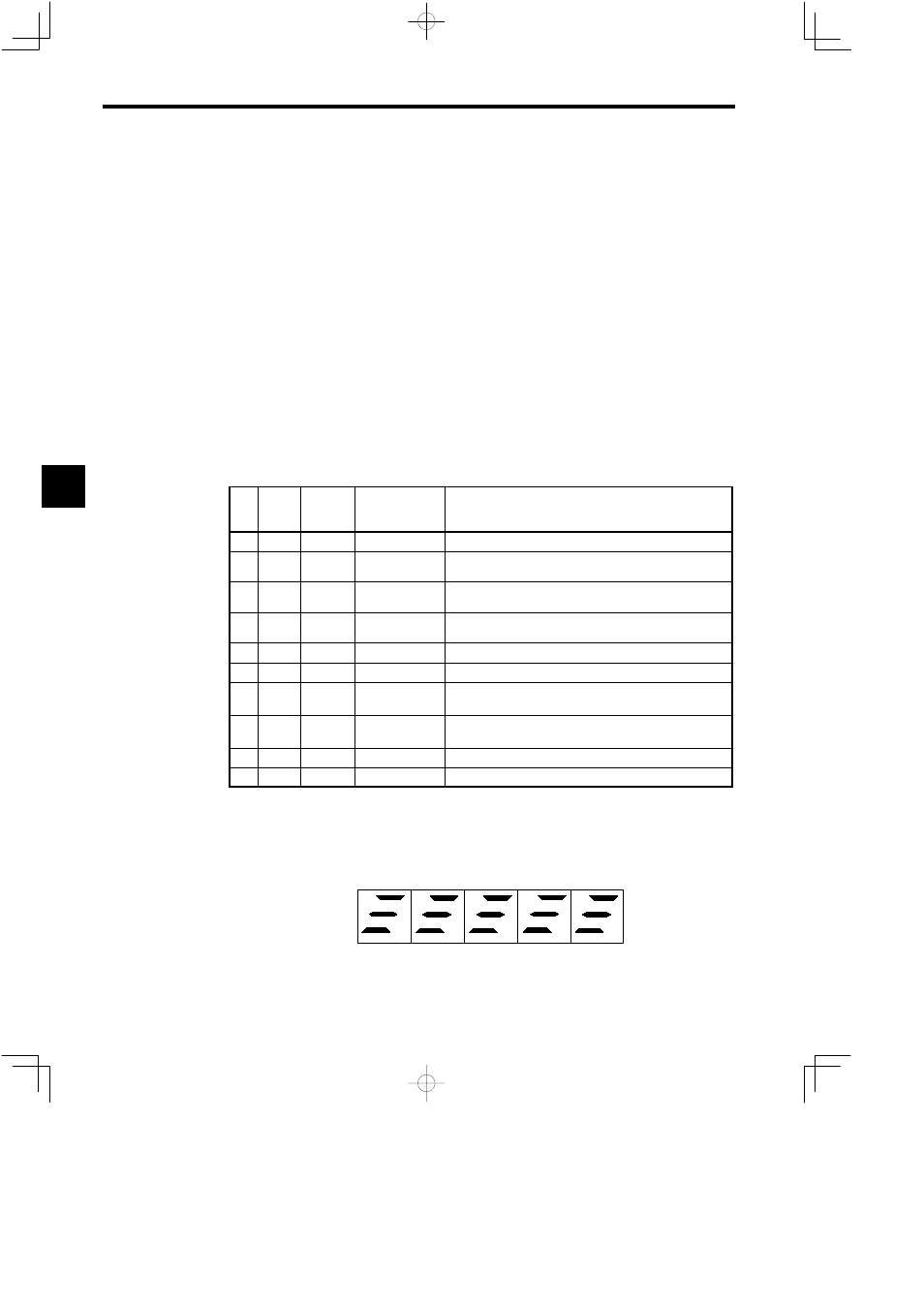
4.4.3 Status Display of Sequence Output Signals
The ON/OFF status of output signals can be checked with the U1-10 operation status display. The LED
indicators on the Digital Operator will light as shown below to indicate signal status. Refer to Section 5
Operating the Digital Operator for operating procedures.
ZSPD
ORG
AGR
ORE
SDET
CHWE
TDET
FLT
TLE
TALM
FC0
FC1
FC2
FC3
FLTL
UI-10
Output signal
status
Note: The LED indicator lights to indicate that the corresponding input signal is ON.
Fig 4.2
Display of Output Signal Status
4