Yaskawa Varispeed 626M5 User Manual
Page 65
3.4 Wiring Control Circuit Signals
3 -25
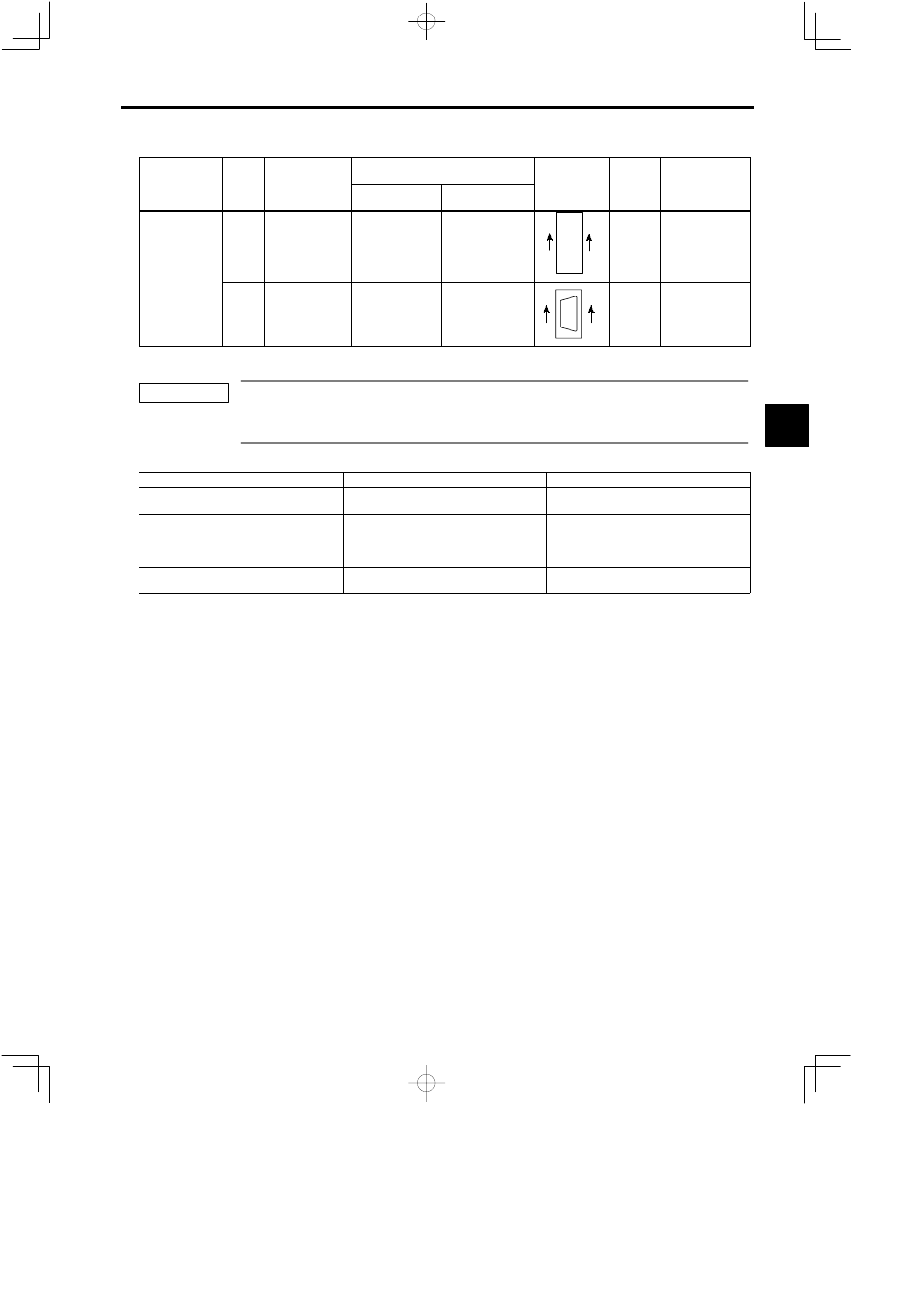
Connector
Manufacturer
Applica-
ble Max.
Wire
Size
Connector Pin
Nos.
Connector Type
Function
Con-
nector
No.
Connector
Manufacturer
Applica-
ble Max.
Wire
Size
Connector Pin
Nos.
Wiring Side
Inverter Side
Function
Con-
nector
No.
Control PC
Board
5CN
(34P)
Control signal
connector with
other drive unit
8831E-034-
170LD
8822E-034-171D
34
32
4
2
33
31
3
1
Use a
special
cable.
KEL Corp.
Board
(VS-656MR5)
1CN
(14P)
Communication
cable connector
(for factory test
prior to shipment)
10214-
52A2JL
S
10114-
3000VE
S
10314-
52A0-008
(case)
14
8
7
1
−
Sumitomo 3M
Ltd.
Note:
Connectors for wires are not sold separated. Refer to 14.3.6 Connector Kit.
Some of the connectors attached with control PC board and option cards are of the same type. Therefore, make
sure to mount the cards to the correct connectors each of which is identified by device symbol. If connection
is wrong, it may cause damage to the inverter.
Table 3.11
Applicable Connector Wires
Connector Number
Cable Specification
Cable External Diameter
1CN (36P)
6CN (50P)
UL2464-SB Vinyl-insulated Multi-conductor
Cable (AWG24)
16 mm (0.63 inches) dia. max.
2CN, 8CN (20P)
9CN, 10CN (14P)
Composite KQVV-SW Cable (AWG22 x 3 C +
AWG26 x 6P)
Yaskawa’s drawing No.: BDP8409123 (with no
connector)
20P: 12 mm (0.47 inches) dia. max.
14p: 8 mm (0.31 inches) dia. max.
4CN (8P)
JKEV-SB (JCS) Shielded Twisted-pair Cable
(AWG18)
11 mm (0.43 inches) dia. max.
3
IMPORTANT