6 precautions for control signal wiring – Yaskawa Varispeed 626M5 User Manual
Page 73
3.4 Wiring Control Circuit Signals
3 -33
3.4.5 Sequence Output Signal Circuit (for Stand-alone Drive)
Design the output signals in consideration of the following conditions.
D
The output method allows either a +24 V or 0 V common.
D
Signal outputs are insulated with photocouplers. Prepare a +24 V power supply for the output signal.
D
The output current capacity is 50 mA at 24 V.
D
To turn ON and OFF an inductive load, such as an external relay, connect a surge absorber in parallel
with the load. The maximum permissible voltage of the output circuit is 26 V. Do not impose a voltage
exceeding the maximum permissible voltage, or otherwise the photocoupler of the output circuit may
be damaged.
D
If the load is capacitive, connect a protective resistor to the load in series to restrict the current, or other-
wise an excessive current will flow when the photocoupler is driven, and as a result, the photocoupler
may be damaged.
D
The following diagram is a sequence output signal circuit.
Fig 3.21
Output Interface Circuit
3.4.6 Precautions for Control Signal Wiring
For proper wiring between devices, pay attention to the following points in the design stage.
D
Design the wiring for control signal lines (1, 2, 4CN) in such a way that they will be separated form
the main circuit wiring (R/L1, S/L2, T/L3) or other power lines.
If the power lines are provided along with the signal lines (motor encoder signal lines), a malfunction may
be caused by the affect of noise generated from the power lines.
D
The length of the control signal lines (including motor encoder signal lines) must be less than 20 m
(65.6 ft).
Excessively long motor encoder signal lines reduce the encoder power supply voltage because of voltage drop
in the signal lines which may cause the inverter to malfunction.
D
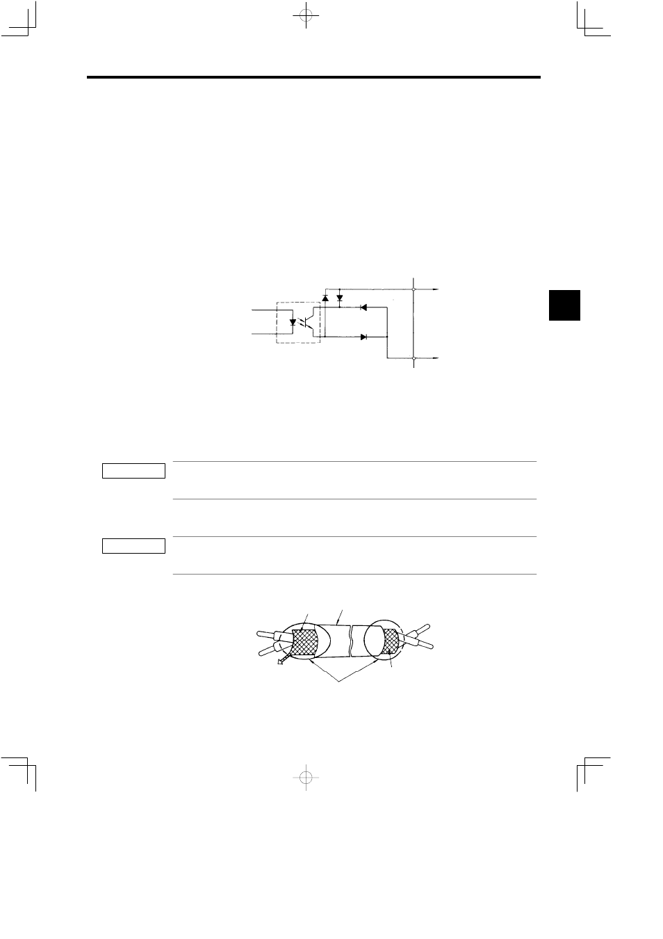
When shielded twisted-pair cables are used for control signal lines, terminate them as shown below.
Shielded Sheath Armor
To inverter shielded
sheath terminal
Insulate these parts
with insulating tape.
Never connect.
Fig 3.22
Shielded Cable Termination
3
IMPORTANT
IMPORTANT