Yaskawa Varispeed 626M5 User Manual
Page 199
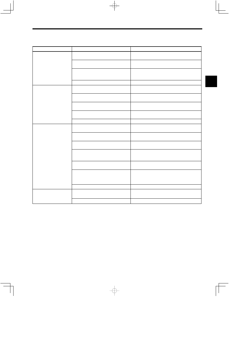
12.4 Motor Faults and Corrective Actions
12 -15
Table 12.3
Motor Faults and Corrective Actions (continued)
Fault
Cause
Corrective Action
Orientation signal ORT is not input.
Confirm that orientation signal ORT is closed on operating
status display (U1-09).
Motor does not stop at
orientation.
Encoder signal line disconnection, improper con-
nection, loose connector
Check the wiring of encoder signal lines.
orientation.
(encoder method orienta-
tion)
Encoder fault
S
Check for abnormal changes in motor speed on the speedom-
eter or operating status display (U1-01).
S
Replace the encoder or the motor.
Fault of Orientation Card or control PCB
Replace the Orientation Card or the control PCB.
Orientation signal ORT is not input.
Confirm that orientation signal ORT is closed on operating
status display (U1-09).
Motor does not stop at
i
i
Incorrect transmission ratio setting
Check the machine data for transmission ratio values (C1-27
to 29).
p
orientation.
(magnetic sensor method
orientation)
Magnetic sensor signal line disconnection, im-
proper connection, loose connector
Check the wiring of magnetic sensor signal lines.
orientation)
Fault of magnetic sensor or magnetizer
Rotate the load shaft and verify that ORG signal lights once
per rotation on operating status display (U1-10).
Fault of Orientation Card or control PCB
Replace the Orientation Card or the control PCB.
Incorrect setting of stop position reference
Check whether the position reference is correct on operating
status display (U2-04).
Incorrect selection of binary/BCD reference or in-
correct setting of BCD reference resolution
Check the setting of control constants C2-22 bit 3 and
C2-12.
Incorrect selection of reference point at incremen-
tal positioning
Check the setting of control constant C2-22 bit 5.
Stop position differs from
commanded position.
(encoder method orienta-
ti )
Improper setting of load shaft zero-point position
S
Perform positioning at zero-point to measure position accu-
racy.
S
Perform tuneup again to set the load shaft zero point.
tion)
Encoder signal line disconnection, improper con-
nection, loose connector
Check the wiring of encoder signal lines.
Malfunction due to noise
(Poor encoder characteristics)
S
Confirm that encoder signal lines are separated from Inverter
output wiring or other power lines.
S
Check encoder cable specifications (whether the cable is a
shielded twisted-pair cable).
Control PCB fault
Replace the control PCB.
Stop position differs from
commanded position.
(magnetic sensor method
Magnetic sensor signal line disconnection, loose
connector
Check the wiring of magnetic sensor signal lines.
(magnetic sensor method
orientation)
Fault of Orientation Card or control PCB
Replace the Orientation Card or the control PCB.
12