7 noise filters (input), Mr connector shapes, Specifications – Yaskawa Varispeed 626M5 User Manual
Page 266
Specifications
14.3.7 Noise Filters (Input)
14 -62
J
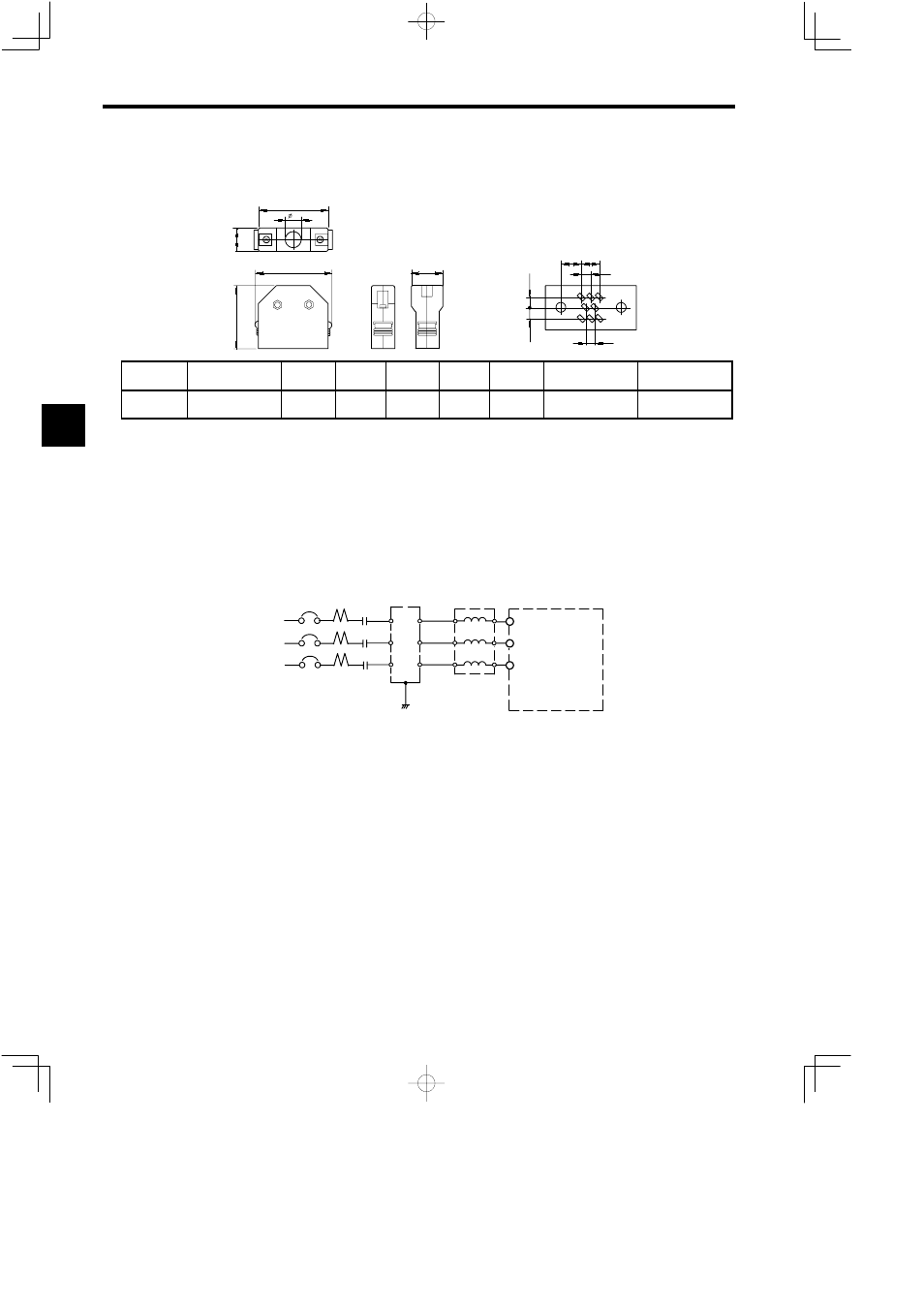
MR Connector Shapes
The MR connector shapes and specifications are shown in the following diagram.
6.1 (0.24) 5.2 (0.2)
2.6 (0.1)
1
2 3
4
5
6
7
8
HONDA
A
D
B
E
C
B
Unit: mm (inches)
8 (0.31)
MR-jL
HONDA
2.6 (0.1)
3
(0.12)
3
(0.12)
No. of
Cores
Product Name
A
B
C
φD
E
Relevant Connec-
tor Number
Manufacturer
8
MR-8LFG
31.0 (1.22) 19 (0.75)
39.8 (1.57) 11 (0.43)
36.6 (1.44) 4CN
HONDA TSUSHIN
KOGYO CO., LTD.
Fig 14.27 MR Connectors
14.3.7 Noise Filters (Input)
Reduce radio noise by using a filter that suppresses transmission of high-frequency noise generated by the
Inverter to the power supply. If used in a location where magnetic field strength is weak, installing an input
noise filter is effective for suppressing electrical interference of televisions and radios.
Select an appropriate input noise filter from the tables 13.28 to 13.31 depending on the Converter model
(VS-656MR5).
IN 1
2
3
4
5
6
Input
noise
filter
U
V
W
X
Y
Z
R
S
T
R/L1
S/L2
T/L3
Converter
VS-656MR5
MCCB
Magnetic
contactor
AC Reactor
Connection Example
Note: Do not connect the input noise filter to the Inverter outputs (U, V. and W).
14