Grounding – Yaskawa Varispeed 626M5 User Manual
Page 63
3.3 Wiring Main Circuit Terminals
3 -23
Strict Prohibition of Installation of Magnetic Starter
Do not connect a phase advancing capacitor or LC/RC noise filter to the output circuit, or otherwise the
Inverter may be damaged or the internal parts of the Inverter may be damaged.
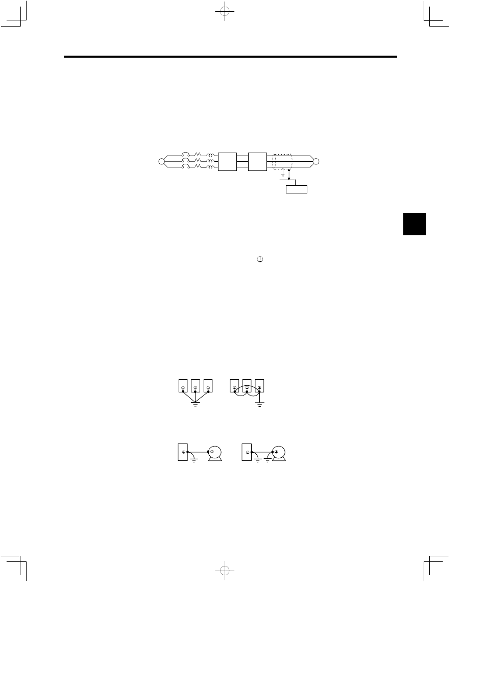
Dealing with Emission Noise
To reduce the emission noise from output side, wire the signal lines together in a grounded metallic con-
duit. Make the wiring distance between the power line and signal line 30 cm (11.8 inches) or longer, and
the emission noise will be reduced.
Power
Supply
MCCB
SignalLine
Control Device
Metallic
Conduit
30 cm (11.8 inches) or longer
~
VS-
656MR5
VS-
626M5
M
Fig 3.15
Dealing with Emission Noise
Wiring Distance between Inverter and Motor
The signal and power cables between the inverter and the motor must be separated and the cable extension
must be as short as possible (20 m (65.6 ft) or less).
J
Grounding
Use the following information to ensure that the ground is sufficient.
D
Make sure to ground the ground terminal ( ).
200 V class: Ground to 100Ω or less
400 V class: Ground to 10Ω or less
D
Never ground the inverter or the converter in common with welding machines, motors, or other large-
current electrical equipment. Wiring for grounding cable must be separated from the large-current
electrical equipment.
D
Always use a ground wire that complies with technical standards on electrical equipment. Minimize
the length of the ground wire. Leakage current flows through the Inverter. Therefore, if the distance
between the ground terminal and the ground terminal is too long, the potential on the ground terminal
of the Inverter will become unstable.
D
Always ground converters, inverters and motors using a ground terminal even when equipment is
grounded through sill channel or steel plate.
D
Ground each Converter and Inverter directly to the ground as shown in figure 3.16 (a). Do not make
a loop as shown in (b). Ground the Inverter and motor as shown in figure 3.17 (a). Do not ground both
the Inverter and motor as shown in (b).
(a) Acceptable
(b) Not Acceptable
Correct
Incorrect
Fig 3.16
Grounding
(a) Acceptable
(b) Not Acceptable
Correct
Incorrect
Fig 3.17
Grounding of Motor and Inverter
3