8 mounting precautions – Yaskawa Varispeed 626M5 User Manual
Page 160
9.8 Mounting Precautions
9 -11
9.8
Mounting Precautions
Pay attention to the following precautions when mounting the Magnet and Magnetic Sensor.
J
Mount the Magnet to the Load Shaft
The position control loop is configured using the detection magnetic field of the Magnet. Mount the Mag-
net on the load shaft (e.g., the main shaft of the machine-tool). If using a belt gear transmission mechanism
between the shaft to which the Magnet is mounted and the load shaft, there is a risk that the stop position
will be out of alignment due to the load shaft belt slipping or gear backlash.
J
Do Not Install a Magnetic Body Near the Magnet
Use non-magnetic materials for the rotator to which the Magnet is mounted. Also make sure that there are
no iron particles sticking to the Magnet. The presence of a magnetic body near the Magnet may warp the
magnetic field, resulting in incorrect position detection and preventing the shaft from stopping in the cor-
rect stop position. Do not place devices that emit magnetic fields (solenoids, magnetos, etc.) near the Mag-
net and Magnetic Sensor, as the presence of another magnetic field near the Magnet may warp the magnetic
field, resulting in incorrect position detection and preventing the shaft from stopping in the correct stop
position.
J
Take Care When Handling the Magnet and Magnetic Sensor
When mounting the Magnet and Magnetic Sensor, do not damage them. The Magnet rotates at high speed,
so damage can result in unexpected accidents. Also, the Magnetic Sensor is a high-precision device, so
if external force is applied resulting in internal distortion, detection accuracy will be reduced.
J
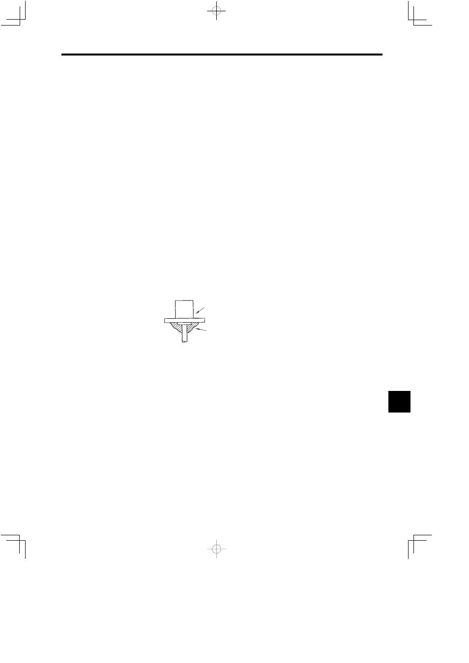
Do Not Subject the Magnetic Sensor Amplifier or Connector Cables to Oil or
Water
Do not allow oil or water to come into contact with the Magnetic Sensor amplifier or connector cables.
If water or oil comes into frequent contact with the sensor head in particular, perform waterproof counter-
measures on the bushings using additional materials, as shown in figure 9.14. If dirty oil or water permeates
the Magnetic Sensor or connector cables, there is a risk that insulation will be reduced, resulting in abnor-
mal signal detection and abnormal control operations.
Magnetic Sensor
Silicon adhesive
Fig 9.14
Magnetic Sensor Bushing Waterproofing Method
J
The Wiring Distance: 20 m. Max.
Make sure that the wiring distance between the Magnetic Sensor Amplifier and the Orientation Card is
20 m maximum. The Magnetic Sensor detection signal is low-voltage, so if the wiring is too long, the sen-
sor will be easily affected by differential voltages and noise voltages, resulting in inaccurate positioning.
J
Be Careful of Polarity
When mounting the Magnet and Magnetic Sensor, pay attention to the polarity, and mount the devices cor-
rectly as shown in the Fig 9.15. Even if the devices are mounted with the polarity mistakenly reversed, the
Orientation Card will still respond to signals, so control will be possible.
9