Unit installation, Busbar mounting, Flat cable mounting – Yaskawa Varispeed 626M5 User Manual
Page 257
14.3 Options and Peripheral Units
14 -53
J
Unit Installation
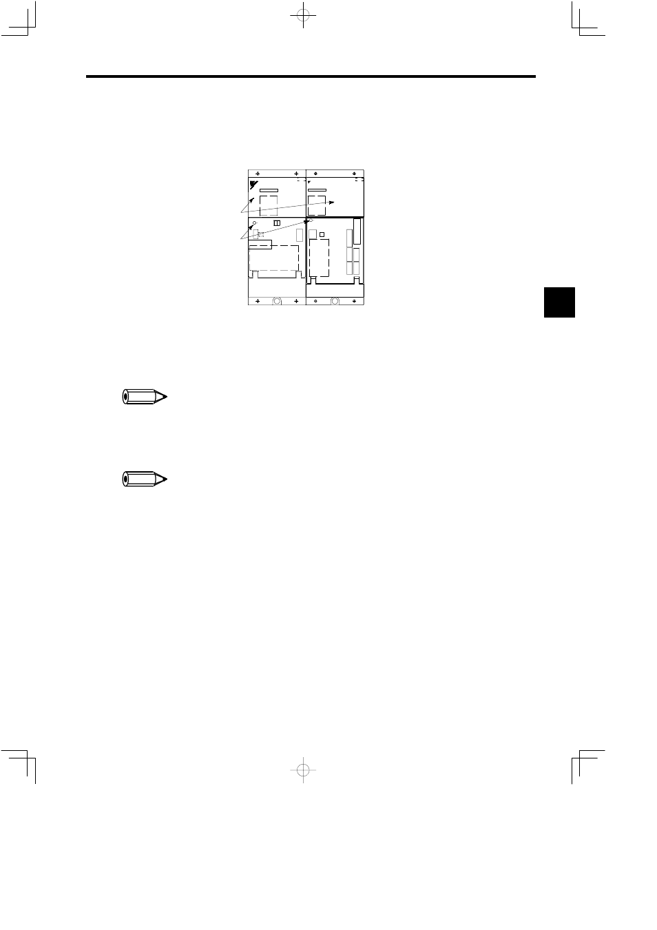
An example combination of a 200-V, 22-kW Converter and a 200-V, 22-kW Inverter is shown in the fol-
lowing diagram. Always install the Converter on the left when viewed from the front.
YASKAWA
Inverter
VS−626M5
YASKAWA
Converter
VS−656MR5
CHARGE
CHARGE
Converter
Inverter
Upper
covers
CHARGE
indicators
SERVOPACK
Fig 14.18 Unit Mounting
J
Busbar Mounting
Use the following procedure to mount the Busbar.
1. Turn OFF the power supply to the Converter, and wait at least 5 minutes (until the CHARGE indicator
is no longer lit) before opening the upper cover.
2. Remove the Converter and Inverter power supply terminal screws, and connect the Busbar.
Be sure to use all of the power supply terminal screws supplied to mount the Busbar, and tighten the screws firmly to a torque
of 4 to 5 NSm.
J
Flat Cable Mounting
Use the following procedure to mount the flat cable.
1. Connect the cable with the red line facing down.
2. Connect the Inverter using the left connector of the two connectors.
When inserting the connectors, check that the clasp locks with a snap.
14
INFO
INFO