Yaskawa Varispeed 626M5 User Manual
Page 277
15.1 Inverter Drive Basics
15 -5
N
r
: Rotator speed (min
−1
),
f: Power supply frequency (Hz), P: No. of motor poles
Also, switching to 3-phase alternating current will reverse the order of the phases, causing the rotation
magnetic field to rotate in reverse, so the motor will rotate in reverse.
In this way, the squirrel cage induction motor changes slip to meet the required torque, generates the re-
quired primary current, and functions as an energy converter that converts electric power (electrical ener-
gy) to to torque and speed (mechanical energy). Differing from the DC motor, however, there is the prob-
lem that the magnetic flux of the rotation magnetic field and the secondary current cannot be controlled
directly, so careful planning for the control is required.
15.1.4 Controlling an Induction Motor Using Vector Control
Vector control permits controls equivalent to the DC motor in a squirrel cage induction motor. This control
method is called slip frequency control, it requires a speed detector, and it performs control taking the de-
tected speed as a standard. Nearly all vector control inverters in use employ this method.
Vector control uses applies the torque generation principle of the squirrel cage induction motor to inverter
control. Primary current I
1
, which is supplied to the induction motor in line with the torque references, is
distributed to secondary current I
2
and magnetized current I
m
as per the set value inside the motor, and
performs control so that the required torque is generated.
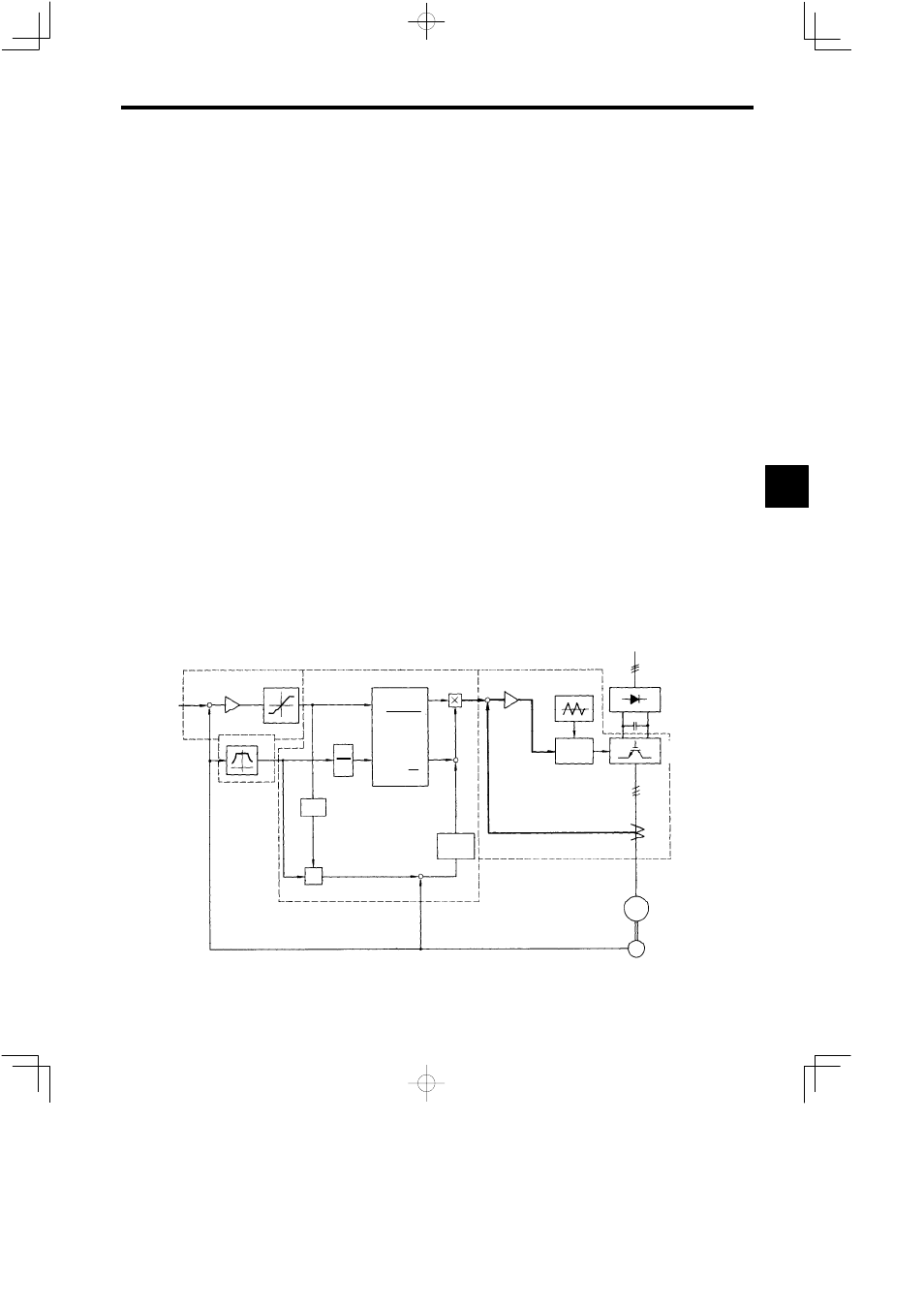
The VS-626M5 control block is shown in Fig. 15.6.
The speed controller performs control so that there is no difference in speed reference value ω
r*
and
speed
detection value ω
r
according to the speed detector signal, and outputs secondary current reference value
I
2
* using a secondary current reference limiter. Rated speed settings and speed adjustment parameters are
used to standardize the signals. The speed controller gain and integral time can be selected to suit the con-
trol mode.
The magnetic flux reference part inputs the speed detection value ω
r
and outputs the magnetic flux refer-
ence value φ* to control fixed outputs.
The vector controller develops the torque generation principle. Primary current reference value I
1
*, and
its frequency and phases, are generated from secondary current reference value I
2
*, magnetic flux refer-
ence value φ*, and speed detection value ω
r.
Use the motor codes to select the parameters depending upon
the motor model.
Current flows through the current controller according to primary current reference vector
1
*
I
S
, and per-
forms control to generate the required torque.
Speed
refer-
ence
Speed controller
Torque limiter
Speed control
Vector control
Current control
Magnetic flux
reference
1
M
R
2
s
dt
ω
r
*+
+
+
ω
r
ω
r
ω
s
I
I
+
−
−
+
+
*
2
1
*
1
*
1
*
1*
m
*
θ
1
φ*
θ=
I
Current
reference
tan
−1
I
*2
2
+ I
*2
m
=
I
*
2
I
m
2
V
PWM
control
VS-656MR5
Converter
VS-626M5
Inverter
CT
M
E
Induction motor
Encoder
Current controller
θ
S
S
I
1
I
S
I
Fig 15.6 VS-626M5 Control Block
15