2 digital i/o configuration, Figure 15: register pdi, Digital i/o configuration – BECKHOFF EtherCAT IP Core for Altera FPGAs v3.0.10 User Manual
Page 55
IP Core Configuration
Slave Controller
– IP Core for Altera FPGAs
III-43
5.2.5.2
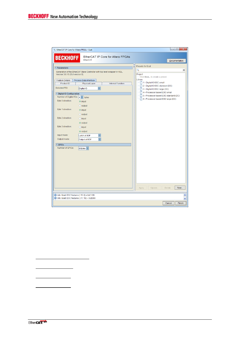
Digital I/O Configuration
The Digital I/O PDI supports up to 4 Bytes of digital I/O signals. Each byte can be assigned as input or
output byte.
Figure 15: Register PDI
– Digital I/O Configuration
Number of digital I/Os
Total number of I/Os. Possible values are 1, 2, 3 or 4 Bytes.
Byte 0-3 direction
Defining byte-wise if digital I/Os are used as input or output byte
Input Mode
Defines the latch signal which is used to take over input data.
Latch at SOF (Start of Frame)
The inputs are latched just before the data have to be written in the frame.
Latch with ext. signal
Connected to DIGI_LATCH_IN. Application controls latching
Latch at Dist-Sync0
Latch input data with distributed clock Sync0 signal
Latch at Dist-Sync1
Latch input data with distributed clock Sync1 signal