3 µcontroller configuration (8/16bit), Figure 16: register pdi, Μc-configuration – BECKHOFF EtherCAT IP Core for Altera FPGAs v3.0.10 User Manual
Page 57
IP Core Configuration
Slave Controller
– IP Core for Altera FPGAs
III-45
5.2.5.3
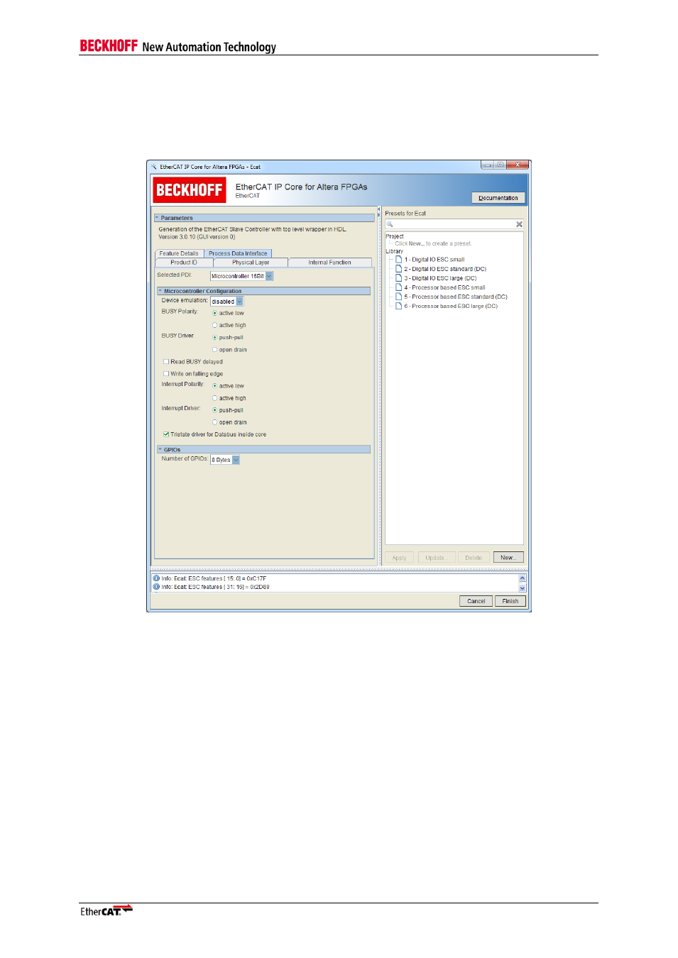
µController Configuration (8/16Bit)
The 8/16 Bit µController interface is an asynchronous parallel interface for µControllers. The difference
between 8 and 16 bit interface is the extended data bus and the BHE signal which enables access to
the upper byte.
Figure 16: Register PDI
– µC-Configuration
Device emulation
Enable Device emulation (0x0141[0]=1). This feature should be disabled in most use cases.
BUSY Polarity, BUSY Driver
Electrical definition of the busy signal driver
Read BUSY delayed
Delay the output of the BUSY signal by ~20 ns (refer to register 0x00152.0).
Write on falling edge
Start write access earlier with falling edge of nWR. Single write accesses will become slower, but
maximum write access time becomes faster.
Interrupt Polarity, Interrupt Driver
Electrical definition of the interrupt signal driver
Tristate driver for data bus inside core
If Tristate drivers for the data bus should be integrated into the IP Core already activate the check box.