Power output, Ring generator, Load regulation – Verilink XEL XSP-100 SHARK IAP (9SA-USRS-9.0R1.02) Product Manual User Manual
Page 209: Output noise, Input voltage, Fcc required emi filters, Power output -9, Fcc required emi filters -9, Igure, Ower module
Chapter 9- Hardware Specifications
SHARK™ IAD User's Guide XEL P/N & Release: 9SA-USRS-9.0R1.02 Chapter 9-9
P
OWER
O
UTPUT
+5vdc
20 Watts
-24vdc
20 Watts
Ring Generator
Ringing
65 V RMS 15 VA
Ringer
Equivalency
Number
15 REN
No more than 5
per line.
+5vdc
< 10%
Load Regulation
-24
< 5%
Ringing
70
± 3 vrms
+5vdc
< 25 mvp-p
Output Noise
-24
< 25 mvp-p
Ringing
< 5% THD
Input Voltage
-42 vdc to -56 vdc
FCC
REQUIRED
EMI
FILTERS
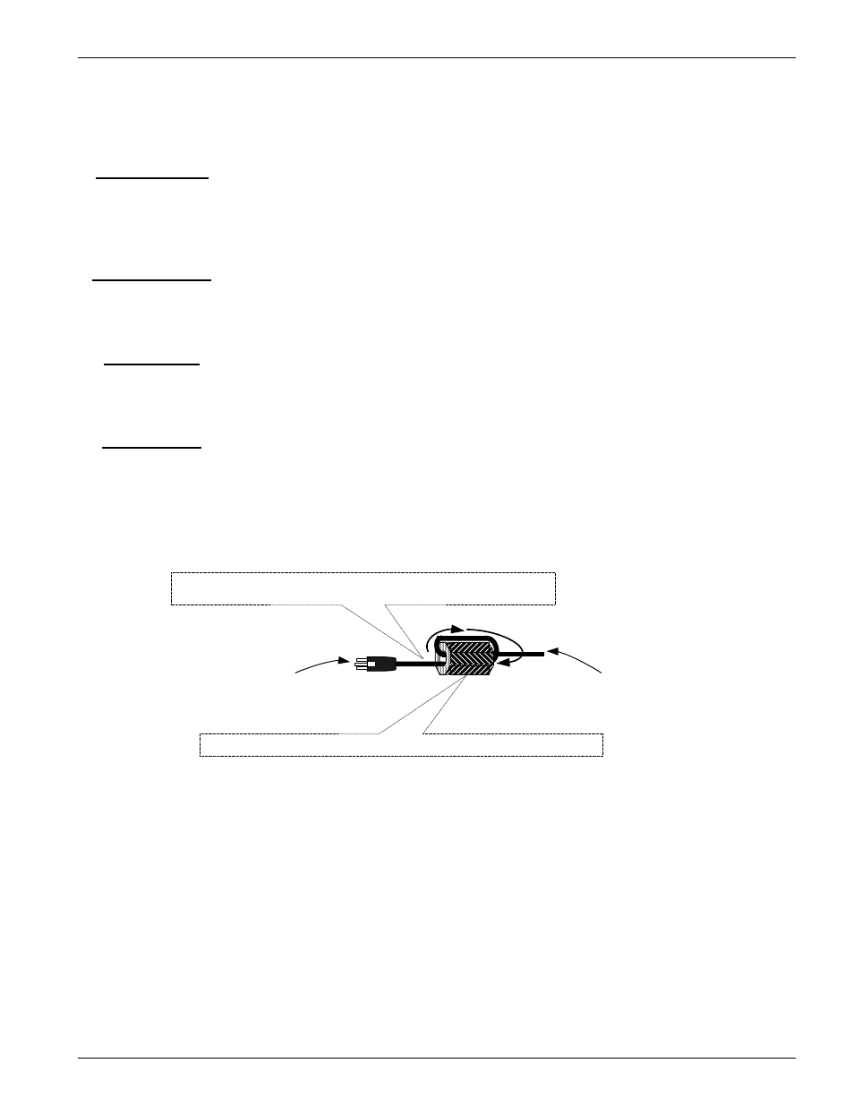
Figure 5 shows how to install the EMI Filters that come with the Power module.
Failure to install these filters as shown may void the FCC licensing of your
SHARK™ IAD unit.
Fcc requirements are that the EMI filter be installed by the customer
approximately 2" to 3" from the end of the DC input cable as shown.
DC power cable from the AC External
Power supply 9SA-PWEX-000. Loop
cable as shown.
DCV Power connector that
connects to Power module
9SA-PW00-000
XEL part number 180-A2003-01 supplied with module 9SA-PW00-000
Figure 5:
Power module DCV power cable EMI filter installation