Faceplate indicators, User connector pinout, Faceplate indicators -28 user connector pinout -28 – Verilink XEL XSP-100 SHARK IAP (9SA-USRS-9.0R1.02) Product Manual User Manual
Page 228: Igure, Emale, Elco, Fxs/dpo 2w p, Ort connector, Able, Ort connector pin definitions
Chapter 9- Hardware Specifications
Chapter 9-28 XEL P/N & Release: 9SA-USRS-9.0R1.02 SHARK™ IAD User's Guide
There are two LEDs on the faceplate: Busy and Fail
Busy
This LED illuminates solid green when at least one of this module's
circuits is off hook. It will flash during power up and or self test.
Fail
This LED is off during normal operation.
A solid red indication on this LED indicates that the module is in a
severe hardware failure determined by a self-test failure.
Note: that a Cross Connect module failure may also cause this
module to fail its self-test causing this LED to illuminate solid red.
A flashing red indication on this LED indicates that the module is
in self-test mode.
Faceplate
Indicators
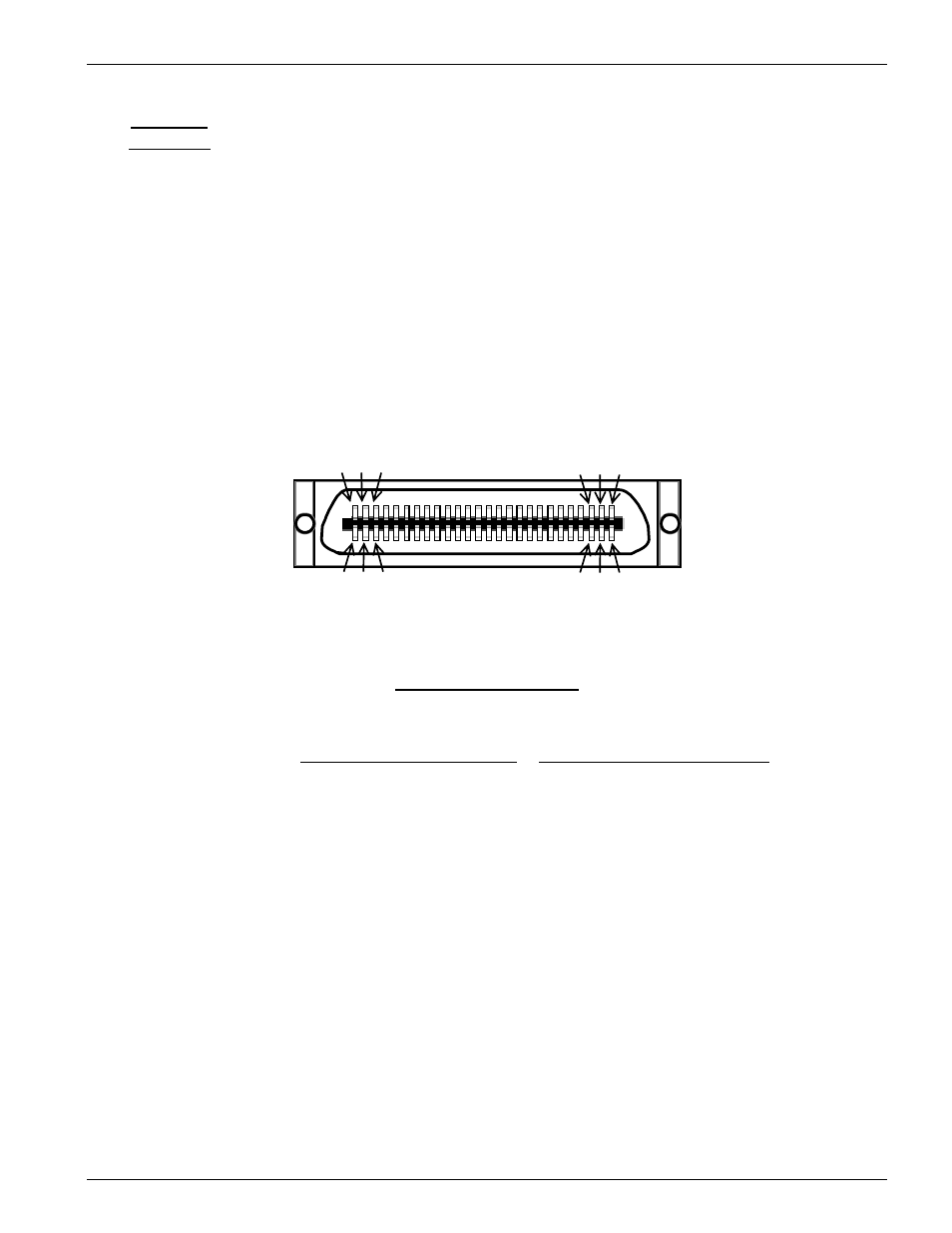
50 Pin Recepticle
1 2 3
23 24 25
26 27 28
48 49 50
Figure 22:
50 pin Female Telco FXS/DPO 2W Port connector
User Connector Pinout
Table 7:
50 pin FXS/DPO 2W Port connector pin definitions
Pin #
Signal Name
Pin #
Signal Name
1
Tip1
26
Ring1
4
Tip2
29
Ring2
7
Tip3
32
Ring3
10
Tip4
35
Ring4
13
Tip5
38
Ring5
16
Tip6
41
Ring6
19
Tip7
44
Ring7
22
Tip8
47
Ring8
Mounting
screw
Chassis gnd
2, 3, 5, 6, 8, 9, 11, 12, 14, 15, 17, 18, 20, 21, 23,
24, 25, 27, 28, 30, 31, 33, 34, 36, 37, 39, 40, 42,
43, 45, 46, 48, 49, 50
N/C