Power dissipation, Compliance, Emi filtering – Verilink XEL XSP-100 SHARK IAP (9SA-USRS-9.0R1.02) Product Manual User Manual
Page 223: Igure, Cat 5, Cable used for, Transmission, Filter installation
Chapter 9- Hardware Specifications
SHARK™ IAD User's Guide XEL P/N & Release: 9SA-USRS-9.0R1.02 Chapter 9-23
LPBK:
This indicator illuminates Green when the T1 circuit is in Loop back.
As there is two T1 circuits on this module, there are two LPBK
indicators. One of them is for the T1-1 circuit and the other for the
T1-2 circuit.
Power Dissipation
Maximum power dissipation is 3.5 Watts
Compliance
WAN module interfaces comply with the applicable sections of the following
standards:
ANSI T1.403-1995
ANSI T1.403-1995
ANSI T1.231-1993
AT&T TR 62411 (12-90)
AT&T TR 54016.
This interface card will also, as part of the IAD, comply with and pass the
applicable required tests specified in the following documents:
FCC Part 68,
CS-03
UL (1950)
Bellcore (GR-1089-CORE, for type 1 units)
EMI Filtering
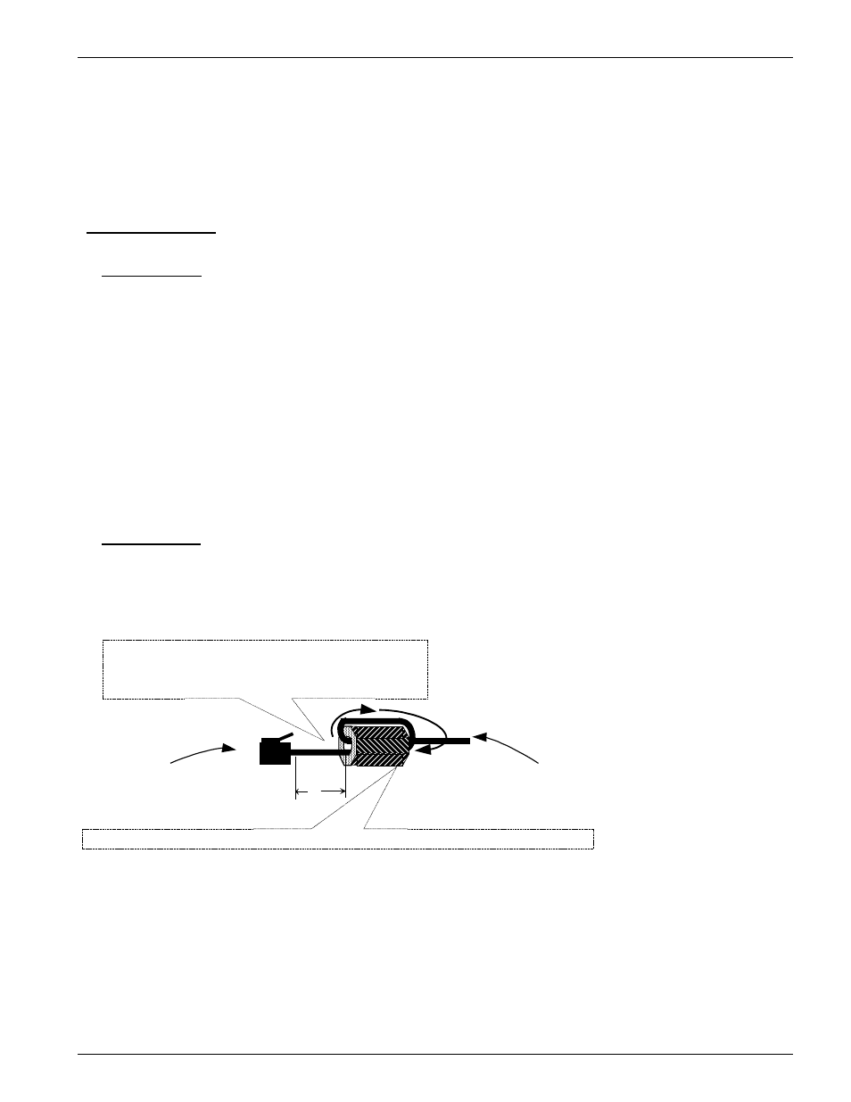
An EMI filter is shipped with every T1 module. Install this filter as shown in
Figure 20. Failure to install these filters as shown may void the FCC licensing
of your SHARK™ IAD unit.
Figure 17:
CAT 5 cable used for T1 transmission EMI filter installation.
CAT 5 cable transporting
T1 signals. Loop cable
through the filter as shown.
T1 connector that
connects to T1 module
9SA-XC2T-V01
XEL part number 180-A2003-01 supplied with module 9SA-XC2T-V01
2"
FCC requirements are that the EMI filter be
installed by the customer approximately 2" from
the end of the T1 input cable as shown.