T1 connector pinout, Faceplate indicators, Power dissipation – Verilink XEL XSP-100 SHARK IAP (9SA-USRS-9.0R1.02) Product Manual User Manual
Page 225: Compliance, Part history, Igure, Connector, Able, And monitor connectors pin definitions
Chapter 9- Hardware Specifications
SHARK™ IAD User's Guide XEL P/N & Release: 9SA-USRS-9.0R1.02 Chapter 9-25
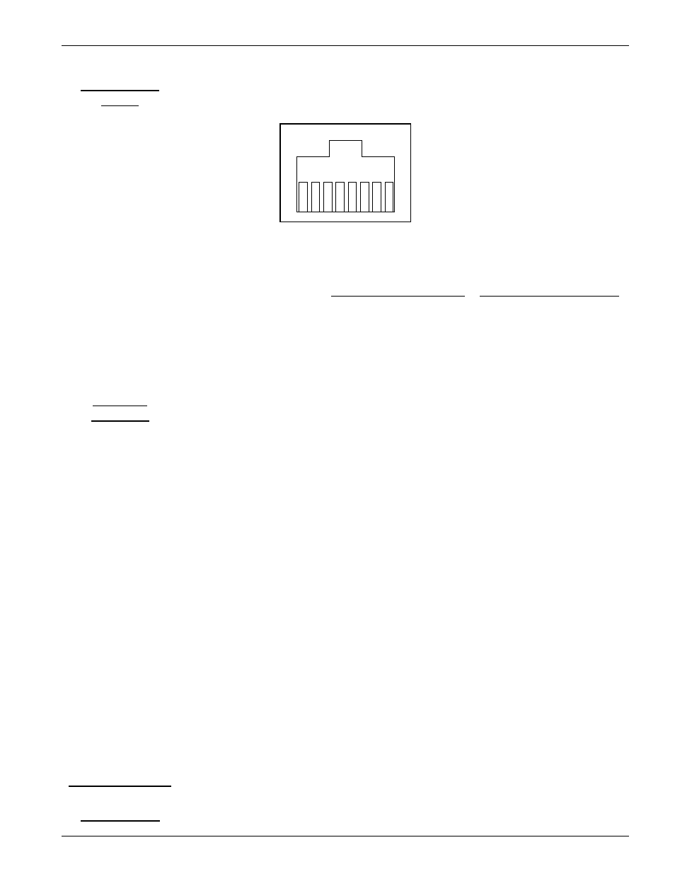
T1 Connector
Pinout
4
5
6
8
1
3 2
7
Figure 19:
T1 connector
Table 6:
T1 and monitor connectors pin definitions
Pin
Signal Name
Pin
Signal Name
RJ-48C T1
1
R
4
R1
2
T
5
T1
3
N/C
6,7,8
N/C
Monitor Interface RX
Tip
Receive in T
Ring
Receive in R
Monitor Interface TX
Tip
Transmit Out T
Ring
Transmit Out R
LOC:
This indicator illuminates Red when a Local Alarm is present. These
are also known as RED Alarm. Local alarms are the result of Loss of
Framing detection and Loss of Signal detection. An AIS signal which
normally is an all ones pattern without T1 framing, will indicate a
LOC alarm also. When the LED is on, an alarm indication will be
sent to the Cross Connect card.
Note: This LED will also stay on if it was on before the loopback of
either Framer or Local is initiated and the loop path is good. During
this condition no alarm condition will be sent to the Cross Connect
card.
Note: Placing the card in the non-operational mode will prevent this
alarm from being displayed on the Cross Connect card.
Faceplate
Indicators
REM:
This indicator illuminates Remote when a Yellow Alarm is received.
It is also known as YELLOW ALARM. When the LED is on, an
alarm indication will be sent to the Cross Connect card.
Note: Placing the card in the non-operational mode will prevent this
alarm from being displayed on the Cross Connect card.
LPBK:
This indicator illuminates Green when the card is in Loop back.
Power Dissipation
Maximum power dissipation is less than one Watt
Compliance
WAN module interfaces comply with the applicable sections of the following