V.35 connections, Sample cross connect, Trunk processing configuration module – Verilink XEL XSP-100 SHARK IAP (9SA-USRS-9.0R1.02) Product Manual User Manual
Page 75: V.35, Connections, Ample, Ross, Onnect, Igure, Onnected
Chapter 5: Graphical User Interface (GUI/WEB) Configuration Pages
SHARK™ IAD User's Guide
XEL P/N & Release: 9SA-USRS-9.0R1.02
Chapter 5-21
V.35
CONNECTIONS
The cross connects for the V.35 card must have the Destination Time Slots in
sequential order and be contiguous. They also must not wrap around from
Destination Time Slot 24 to Destination Time Slot 1 to complete the bandwidth.
S
AMPLE
C
ROSS
C
ONNECT
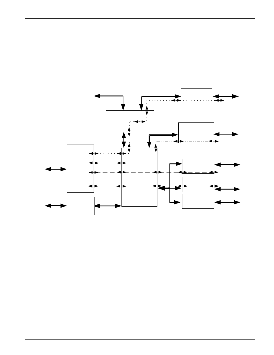
Figure 18 shows how the connections shown in Figure 15 are implemented
throughout the system.
Figure 18:
Cross Connected Data paths through the SHARK™ IAD
Figure 18 is a visual representation of four possible connections through the
SHARK™ IAD system. The programming of these connections is shown in
Figure 15.
•
The dotted line:
• • • indicates the path that a six DS0 connection would
traverse from the time slots 19 through 24 of WAN module 1 through the
router and out the 10/100BaseT Ethernet port as un-channelized packetized
data.
•
The dashed line:
indicates the path that an eight DS0 connection
would traverse from the time slots 1, 2, 3, 4, 7, 8, 9 and 11 of WAN module 1
to the Voice 1 module for circuits 1 through 8.
•
The dash-dot line:
• • indicates the path that a four DS0 connection
SUPER
SPEED
PCM BUS
10/100
ETHERNET
VF MODULE 1
VF MODULE 2
VF MODULE 3
WAN 2
BUS
WAN
MODULE 2
RS-232
CRAFT
INTERFACE
WAN1-TS: 19-24
WAN1-TS: 19-24 x to
Router-CH: 1-6
Router-CH :1- 6
10/100 Ethernet
Unchannalized data
WAN
MODULE 1
I/P
ROUTER/
BRIDGE
DIGITAL
CROSS CONNECT
WAN1-TS:1-4,
7-9, 11
8 DSOs
8 DSOs
8 DSOs
8 USER
VF
PORT
8 USER
VF
PORT
8 USER
VF
PORT
24
DS0
VOICE
BUS
DATA or T1
INTERFACE MODULE
USER
V.35
or
FT1
PORT
T1
NETWORK
T1
NETWORK
WAN1-TS 1-4, 7-9, 11 x to
Voice 1: CH: 1-8
NOTE: The following nomenclature WAN1-TS:0 refers to the time slot 0 coming out of WAN1
WAN1-TS: 5-6,
10, 12
WAN1-TS 5-6, 10, 12 x to
Voice 2: CH: 1-4
WAN1-TS: 15-18
WAN1-TS 15-18 x to
LAN1-CH: 13-16